
Page 315 - Parker - Parker Pneumatic
P. 315
PDE2600PNUK
Parker Pneumatic Origa OSP-E Electric Linear Actuators
Sizing Performance
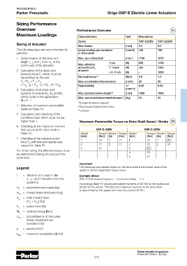
Overview Performance Overview T1
Maximum Loadings Characteristics Unit Description
Series OSP-E20BV OSP-E25BV
Sizing of Actuator Max. Speed [m/s] 3.0 5.0
The following steps are recommended for Linear motion per revolution [mm/U] 108 160
selection : of drive shaft
1. Determination of the lever arm Max. rpm. drive shaft [min ] 1700 1875
-1
length l , l and l from m to the 1m/s [N] 650 1430
e
x
z
y
centre axis of the actuator. Max. effective
action force F A 1 - 2 m/s [N] 450 1200
2. Calculation of the static and at speed > 3 - 5 m/s [N] – 1050
dynamic force F which must be
A
transmitted by the belt. No-load torque 2) [Nm] 0.6 1.2
F = F + F + F Max. acceleration/deceleration [m/s ] 20 20
2
A
g
0
a
= m · g + m · a + M · 2π / U
g g 0 ZR Repeatability +/- 0.05 0.05
3. Calculation of all static and [mm/m]
dynamic moments M , M and M Max. standard stroke length 1) [mm] 1000 1500
z
x
y
which occur in the application. Max. recomended permissible mass 3) [kg] 10 20
M = F · l
1) Longer strokes on request
4. Selection of maximum permissible 2) As a result of static friction force
loads via Table T3. 3) vertical
5. Calculation and checking of the
combined load, which must not be
higher than 1. Maximum Permissible Torque on Drive Shaft Speed / Stroke T2
6. Checking of the maximum moment
that occurs at the drive shaft in OSP-E-20BV OSP-E-25BV
Table T2. Speed Torque Stroke Torque Speed Torque Stroke Torque
[m/s] [Nm] [m] [Nm] [m/s] [Nm] [m] [Nm]
7. Checking of the required action 1 19 1 17 1 36 1 36
force F with the permissible load
A
value from Table T1. 2 17 2 11 2 30 2 36
3 16 3 30
For motor sizing, the effective torque must
be determined, taking into account the 4 28
cycle time. 5 27
Important:
Legend The maximum permissible torque on the drive shaft is the lowest value of the
speed or stroke-dependent torque value.
l = distance of a mass in the Example above:
x-, y- and z-direction from the OSP-E25BV required speed v = 3 m/s and stroke = 1 m.
guide [m]
Accordingly Table T2 shows permissible moments of 30 Nm for the speed and
m = external moved mass [kg] 36 Nm for the stroke. Therefore the maximum moment at the drive shaft
e is determined by the speed and must not exceed 30 Nm.
m LA = moved mass of actuator [kg]
m = total moved mass
g
(m + m ) [kg]
e LA
F = action force [N]
A
M = no-load torque [Nm]
0
U = circumference of the pulley
ZR
(linear movement per
revolution) [m]
g = gravity [m/s²]
a = maximum acceleration [m/s²]
max
Parker Hannifin Corporation
Pneumatic Division - Europe
315