
Page 320 - Parker - Parker Pneumatic
P. 320
PDE2600PNUK
Parker Pneumatic Origa OSP-E Electric Linear Actuators
Sizing Performance
Overview Performance Overview
Maximum Loadings Characteristics Unit Description
Size OSP-E25B OSP-E32B OSP-E50B
Sizing of Actuator Max. speed [m/s] 2 3 5
The following steps are recommended for Linear motion per revolution, [mm] 60 60 100
selection : drive shaft
Max. rpm drive shaft [min ] 2 000 3 000 3 000
-1
1. Required acceleration,
2. Required torque is shown Max. effective < 1 m/s: [N] 50 150 425
on page 332 action force 1- 2 m/s: [N] 50 120 375
3. Check that maximum values in the F at speed > 2 m/s: [N] – 100 300
A
table 3 are not exceeded No-load torque [Nm] 0.4 0.5 0.6
4. Drive shaft by using table T2.
2
(Pay attention to note under table) Max. acceleration/deceleration [m/s ] 10 10 10
If value is lower than required, Repeatability [mm/m] ±0.05 ±0.05 ±0.05
overview the moving profile or Max. stroke length OSP-E..B [mm] 3000 5000 5000
select if possible a bigger unit. Max. stroke length OSP-E..B* [mm] 2 x 1500 2 x 2500 2 x 2500
5. Before sizing and specifying the
motor, the average torque must be * Bi-parting version
calculated using the cycle time T2
of the application. Maximum Permissible Torque on Drive Shaft Speed / Stroke
6. Check that the maximum allowable
unsupported length is not exceeded. OSP-E25B OSP-E32B OSP-E50B
Speed Torque Stroke Torque Speed. Torque Stroke Torque Speed. Torque Stroke Torque
[m/s] [Nm] [m] [Nm] [m/s] [Nm] [m] [Nm] [m/s] [Nm] [m] [Nm]
1 0.9 1 0.9 1 2.3 1 2.3 1 10.0 1 10.0
2 0.9 2 0.9 2 2.0 2 2.3 2 9.5 2 10.0
3 0.9 3 1.8 3 2.3 3 9.0 3 9.0
4 2.3 4 8.0 4 7.0
5 1.8 5 7.5 5 6.0
Important:
The maximum permissible torque on the drive shaft is the lowest value of the
speed or stroke-dependent torque value.
Example above:
OSP-E32B stroke 2 m, required speed 3 m/s;
From table T2: speed 3 m/s gives 1.8 Nm and stroke 2 m gives 2.3 Nm.
Max. torque for this application is 1.8 Nm.
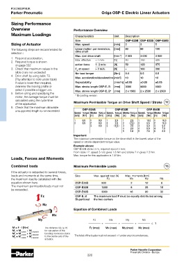
Loads, Forces and Moments
Combined loads Maximum Permissible Loads T3
If the actuator is subjected to several forces,
loads and moments at the same time, Size Max. applied load [N] Max. moments [Nm]
the maximum load is calculated with the Fz Mx My Mz
equation shown here. OSP-E25B 500 2 12 8
The maximum permissible loads must not OSP-E32B 1200 8 25 16
be exceeded.
OSP-E50B 3000 16 80 32
OSP-E..B The maximum load F must be equally distributed among
Bi-partional the two carriers
Equation of Combined Loads
Fz Mx My Mz
+ + + ≤ 1
M = F · l [Nm] The distance l (lx, ly, lz) Fz (max) Mx (max) My (max) Mz (max)
M = M x static + M x dynamic for calculation of the
x
M = M y static + M y dynamic bending moments relates
y
M = M + M to the centre axis of the The total of the loads must not exceed >1 under any circumstances.
z z static z dynamic
actuator.
Parker Hannifin Corporation
Pneumatic Division - Europe
320