
Page 341 - Parker - Parker Pneumatic
P. 341
PDE2600PNUK
Parker Pneumatic Origa OSP-E Electric Linear Actuators
Sizing Performance
Overview Performance Overview
Maximum Loadings Characteristics Unit Description
Size OSP-E25STR OSP-E32STR OSP-E50STR
Sizing of Actuator Pitch [mm] 3 4 5
Max. speed [m/s] 0.075 0.1 0.125
The following steps are recommended for
drive shaft
selection : Linear motion per revolution, [mm] 3 4 5
1. Check that the maximum values in the Max. rpm, drive shaft [min ] 1500 1500 1500
-1
2)
adjacent chart and transverse force/ Max. effective action force F [N] 800 1600 3300
stroke graph below are not exceeded. Corresponding torque A [Nm] 1.35 3.4 9.25
2. Check the lifetime/travel distance in on drive shaft
graph below. No-load torque [Nm] 0.3 0.4 0.5
Max. allowable torque [Nm] 1.7 4.4 12
3. When sizing and specifying the motor, on drive shaft
the RMS-average torque must be Self-locking force F 1) [N] 800 1600 3300
calculated using the cycle time in Typical repeatability L [mm/m] ±0,5 ±0,5 ±0,5
application
Max.Standard stroke length [mm] 500 500 500
1) Related to screw types Tr 12x3, Tr 16x4, Tr 24x5
from 0,4 m stroke max. 1200 min-1 permissible
2)
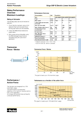
Transverse
Force / Stroke Transverse Force / Stroke
Load
OSP-E25STR
OSP-E25STR
OSP-E32STR
OSP-E32STR
OSP-E50STR
OSP-E50STR
stroke
The graph is based upon 10% intermittent usage
Performance / Performance as a function of the action force
Action Force
Action Force [N]
The Actuators are designed for a 10%
intermittent usage.
The performance to be expected OSP-E50STR
OSP-E50STR
depends on the maximum required actions
force of the application. OSP-E32STR
OSP-E32STR
An increase of the action force will lead to
OSP-E25STR
a reduced performance. OSP-E25STR
Performance [km]
The graph is based upon 10% intermittent usage
Parker Hannifin Corporation
Pneumatic Division - Europe
341