Page 2 - Joyce - Bevel gear jacks
P. 2

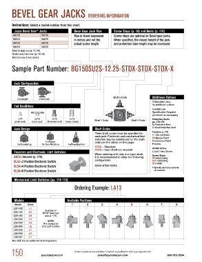
BEVEL gEAR JACKS ORDERiNg iNFORmATiON


        Instructions: Select a model number from this chart.
          Joyce Bevel Gear  Jacks             Bevel Gear Jack Rise    Screw Stops (p. 10) and Boots (p. 170)
                       ®
         Bg150S           Bg150D              Rise is travel expressed    Screw stops are optional on Bevel gear jacks.
         Bg250S           Bg250D              in inches and not the   When specified, the closed height of the jack
         Bg375S           Bg375D              actual screw length.    and protection tube length may be increased.
         Bg450S           Bg450D
         Follow the design tips (pp. 151-154).
         Detailed product information (pp. 155-158).
         Right hand screw threads standard.

        Sample part Number: Bg150Su2S-12.25-STDX-STDX-STDX-X


          Jack Configuration


                                                                      Shaft 2 Code           Additional Options
           U=Upright    I=Inverted
                                                                                             X=Standard Jack,
          End Conditions                                                                     no additional options
                                                                                             S=Additional
                                                                                             Specification Required
                                                                                             (comment as necessary)
            1=T1      2=T2       3=T3      4=T4                                              Protective Boots
          (plain end)  (load pad)  (threaded end)  (male clevis)  Shaft 1 Code   Shaft 3 Code  pp. 170-172
                                                                                             B=Protective Boot
          Jack Design                                      Shaft Codes                       D=Dual Protective Boot
                                                          Three shaft codes must be specified for   Finishes p. 179
                                                          each jack. Electronic and mechanical limit   F1=Do not Paint
                                                          switches may be substituted for the shaft   F2=Epoxy Paint
                             K=Keyed                      code per the tables on this page.  F3=Outdoor Paint
            S=Translating  for Non Rotation  N=Traveling Nut                                 Process
                                                          STDX – Standard
                                                          XXXX – Input shaft not required    ACME Screw
          Encoders and Electronic Limit Switches          When ordering with only one input shaft,    L=Left Hand Screw
          ENCX=Encoder (p. 178)                           it is recommended to order the following    Screw Stops
                                                                                             ST0=Extending
          ELS2=2 Position Electronic Switch               configuration:                     ST1=Retracting
                                                                                             ST2=Both
          ELS4=4 Position Electronic Switch               XXXX-STDX-XXXX                     • Specify as many options
          ELS6=6 Position Electronic Switch                                                     as needed

          Mechanical Limit Switches (pp. 174-175)

                                              Ordering Example: LA13


          Models                          Available Positions
          Model   Code                      1         2       3        4        5         6        7        8
         LS7-402   LI
         LS8-402   LA       Number of
                           DPDT Switches
         LS8-404   LB       (see p. 175)
         LS9-502   LC
                              NOTE:
         LS9-503   LD      Will always be
         LS9-504   LE     0 for LS7 models
         LS9-505   LF
         LS9-506   LG
         LS9-507   LH
         Note: All Bg jacks are available with all mounting positions.


        150               joycedayton.com     Custom products are available • Contact Joyce/Dayton with your requirements  800-523-5204
                                                            sales@joycedayton.com
   1   2   3   4   5   6   7