
Page 3 - Joyce - Bevel gear jacks
P. 3
BEVEL gEAR JACKS SpECiFiCATiONS AND DESigN TipS
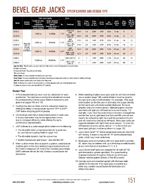
Static Load Capacity Screw
Upright Assembly: Upright Assembly: Bevel Pinion Pinion Jack† Base Add for
Model Dynamic screw-in screw-in tension/ Gear Turns for Torque Screw Jack Cooling Weight Each Inch
Capacity compression/ Inverted Dia. Pitch/Lead Ratio 1" Travel (In. Lbs.) Torque Efficiency Time (Lbs.) of Travel
Inverted Assembly: Assembly: Screw-in (Lbs.)
screw-in tension compression
Bg150-S .375p STuB 2.69:1 7.18 .059w* .151w* 38.5% 38 min. 42 .8
ACmE
14,000 lbs. 14,000 lbs. 1 1/2"
Bg150-D* .250p / .500L 2.69:1 5.38 .066w* .169w* 45.6% 38 min. 42 .8
ACmE 2C
.500p
Bg250-S ACmE 2C 2.15:1 4.31 .111w* .227w* 34.2% 82 min. 140 2.6
30,000 lbs. 30,000 lbs. 2 1/2"
please use .375p / .750L
Bg250-D* JAX V2 ACmE 2C 2.15:1 2.87 .133w* .272w* 42.6% 82 min. 140 2.6
®
Software
Bg375-S or contact .666p 3.52:1 5.29 .098w* .329w* 31.5% 192 min. 230 4.1
Joyce/Dayton 66,000 lbs. 40,000 lbs. 3 3/4" ACmE 2C
Bg375-D* .666p / 1.333L 3.52:1 2.64 .134w* .448w* 46.0% 192 min. 230 4.1
STuB ACmE
Bg450-S .500p ACmE 2C 3:1 6 .125w* .356w* 21.9% 262 min. 650 5.5
218,000 lbs. 200,000 lbs. 4 1/2"
Bg450-D* .500p / 1.00L 3:1 3 .154w* .438w* 35.5% 262 min. 650 5.5
ACmE 2C
Important Note: *Not self-locking, may lower under load. Brake motors or external locking systems are recommended.
D: Double Lead Screws.
S: Single Lead Screws. These jacks are self-locking.
*W: Load in pounds.
Pinion Torque: The torque required to continuously raise a given load.
Screw Torque: The torque required to resist screw rotation (translating jack design) and traveling nut rotation (keyed for traveling nut design).
Lead: The distance traveled axially in one rotation of the lifting screw.
Pitch: The distance from a point on the screw thread to a corresponding point on the next thread, measured axially.
†: Cooling time based on time to cool from 200°F to 70°F (ambient).
Design Tips:
1. A PV (pressure/velocity) value must be calculated for each 6. When selecting multiple bevel gear jacks for an interconnected
application. The continuous running time should not exceed row or system (page 195) careful attention must be given to
the corresponding T (time) value. Refer to instructions and the input and output shaft rotations. For example, if the input
graphs on pages 152 and 153. shaft rotation on the first jack is clockwise, the output shaft(s)
on that same jack will rotate counter-clockwise. To insure
2. Cooling time data on these charts is calculated based on
limiting the lifting nut temperature rise from 70ºF to 200ºF all jacks raise and lower in unison, alternating jacks must be
(100º below dropping point of grease). specified with right and left hand acme screw threads. For
example, if you have five jacks interconnected in a straight line
3. Check single lead versus double lead screws in each case. and the first jack is right hand, the third and fifth jack will also
A double lead screw may be the appropriate choice need to be ordered as right hand and the second and fourth
due to increased efficiency while offering the same jack will need to be ordered as left hand. Bevel gear jacks are
performance characteristics. supplied standard with right hand acme screws. To order the
®
4. JAX software is a useful design aid to determine the following: left hand acme screw option, add an "L" to the end of your
bevel gear jack part number as shown on page 150.
• The allowable static compression load for a given rise
®
(or use Column Loading Chart on page 154) 7. Joyce Bevel Gear “S” Series (single lead) jacks are inherently
self-locking. A brake is required for “D” series (double lead)
• The allowable dynamic load for a given rise jacks, which may lower under load.
• System horsepower and torque – also see item #5 8. Bevel gear jacks are furnished with one input shaft in position
5. When a direct motor drive is used in a system, consideration #2. Jacks may be ordered with up to three input shafts located
must be given to the input starting torque requirements and at any combination of positions # 1, 2, or 3.
the motor horsepower will need to be increased accordingly 9. Joyce Bevel Gear jacks are designed for oil bath (EP-90
®
(JAX software will not do this). Contact Joyce/Dayton for gear lubricant) or grease operation. The upper bearing
®
assistance. is grease lubricated through a fitting on top of the jack.
Grease must be applied directly to the lifting screw.
10. Typically jacks are mounted upright with the base plate
parallel to the horizon. If the base plate is oriented any
other way, contact Joyce/Dayton for lubrication and
other instructions.
2D and 3D models available on website • Ordering information on page 150 151
800-523-5204 sales@joycedayton.com joycedayton.com