
Page 4 - Joyce - Bevel gear jacks
P. 4
BEVEL gEAR JACKS AppLiCATiON iNFORmATiON AND ThERmAL gRAphS
In many applications, Joyce Bevel Gear jacks are more efficient and faster than wormgear driven jacks. To determine
®
the suitability of a bevel gear jack for your application, use the steps below to calculate load, travel speed and duty cycle.
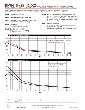
Step 1 Determine load in pounds. Step 6 Plot the points for PV and T on the appropriate graph
(below or on the next page). If the point falls below the
Step 2 Determine velocity in feet / minute (fpm). line, the application is satisfactory. If it is above the line,
recalculate T for the next larger size jack. Each jack size
Step 3 Determine duty cycle in terms of minutes operation / has a different cooling time (p. 151).
minutes resting (or time on / time off).
Step 7 Calculate horsepower.
Step 4 Calculate PV. RPM = Velocity in fpm x 12 x input turns per one-inch
PV = (load x velocity in fpm)/1000 travel (from chart on p. 151)
Horsepower = Pinion torque (from chart) x load x RPM
Step 5 Calculate cooling time (T).
time on
T = Cooling time (p. 151) x
time off
BG150 S and BG150 D Bevel Gear Jacks
Single Lead Screw (lead 0.375 In.)
Double Lead Screw (lead 0.500 In.)
T
PV
BG250 S and BG250 D Bevel Gear Jacks
Single Lead Screw (lead 0.500 In.)
Double Lead Screw (lead 0.750 In.)
T
PV
Note: PV = load x velocity (fpm) T = the max i mum running time in minutes before a complete cooling time is required.
1000
152 joycedayton.com 2D and 3D models available on website • Ordering information on page 150 800-523-5204
sales@joycedayton.com