
Page 409 - Wago_PCB_TerminalBlocksConnectors_Volume2_2015_US
P. 409
"
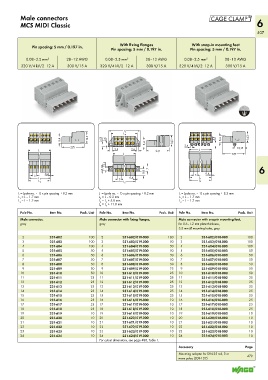
Male connectors
MCS MIDI Classic 6
407
With fixing flanges With snap-in mounting feet
Pin spacing: 5 mm / 0.197 in. Pin spacing: 5 mm / 0.197 in. Pin spacing: 5 mm / 0.197 in.
0.08–2.5 mm 2 28–12 AWG 0.08–2.5 mm 2 28–12 AWG 0.08–2.5 mm 2 28–12 AWG
320 V/4 kV/2 12 A 300 V/15 A 320 V/4 kV/2 12 A 300 V/15 A 320 V/4 kV/2 12 A 300 V/15 A
<__________ __________>
L 5
<________ ________>
(_ 14,3 __) L 4 > > (_ 14,3 __)
>
2,6
8,4 _ __> 8,4 (_ 14,3 __) 4,5 __> 8,4 _
<____ 27,5 ____> 3,55 ___> > _ 2,4 < < < 12,15 <
__> <
<
3,4
<______ L _______> > > <__ 2,6 < <____ 27,5 ____> <______ L _______>
__> <
<______ L _______> <____ 27,5 ____>
2,5 > <__ >
> 5,1 > > 9,8 7 6
0,4 > 0,4
> 5 < __> < > 5 < __> <
<______ ______> > 5 < 0,4 < > <_____ _ ______>
L 1
__>
L 1
<______ ______> <______ ______> <______ ______>
L 2
L 2
L 3
L = (pole no. – 1) x pin spacing + 8.2 mm L = (pole no. – 1) x pin spacing + 8.2 mm L = (pole no. – 1) x pin spacing + 8.2 mm
L = L – 1.7 mm L = L – 0.2 mm L = L – 1.7 mm
1
1
3
L = L – 1.2 mm L = L + 5.8 mm L = L – 1.2 mm
4
2
2
3
L = L + 11.8 mm
3
5
Pole No. Item No. Pack. Unit Pole No. Item No. Pack. Unit Pole No. Item No. Pack. Unit
Male connector, Male connector with fixing flanges, Male connector with snap-in mounting feet,
gray gray for 0.6–1.2 mm plate thickness,
3.5 mm Ø mounting holes, gray
2 231-602 100 2 231-602/019-000 100 2 231-602/018-000 100
3 231-603 100 3 231-603/019-000 50 3 231-603/018-000 100
4 231-604 100 4 231-604/019-000 50 4 231-604/018-000 100
5 231-605 50 5 231-605/019-000 50 5 231-605/018-000 50
6 231-606 50 6 231-606/019-000 50 6 231-606/018-000 50
7 231-607 50 7 231-607/019-000 50 7 231-607/018-000 50
8 231-608 50 8 231-608/019-000 50 8 231-608/018-000 50
9 231-609 50 9 231-609/019-000 25 9 231-609/018-000 50
10 231-610 50 10 231-610/019-000 25 10 231-610/018-000 50
11 231-611 25 11 231-611/019-000 25 11 231-611/018-000 25
12 231-612 25 12 231-612/019-000 25 12 231-612/018-000 25
13 231-613 25 13 231-613/019-000 25 13 231-613/018-000 25
14 231-614 25 14 231-614/019-000 25 14 231-614/018-000 25
15 231-615 25 15 231-615/019-000 25 15 231-615/018-000 25
16 231-616 25 16 231-616/019-000 10 16 231-616/018-000 25
17 231-617 25 17 231-617/019-000 10 17 231-617/018-000 25
18 231-618 25 18 231-618/019-000 10 18 231-618/018-000 25
19 231-619 10 19 231-619/019-000 10 19 231-619/018-000 10
20 231-620 10 20 231-620/019-000 10 20 231-620/018-000 10
21 231-621 10 21 231-621/019-000 10 21 231-621/018-000 10
22 231-622 10 22 231-622/019-000 10 22 231-622/018-000 10
23 231-623 10 23 231-623/019-000 10 23 231-623/018-000 10
24 231-624 10 24 231-624/019-000 10 24 231-624/018-000 10
For cutout dimensions, see page 488, Table 1.
Accessory Page
Mounting adapter for DIN 35 rail, 3 or
more poles (209-137) 479