
Page 586 - Wago_PCB_TerminalBlocksConnectors_Volume2_2015_US
P. 586
13 Tests and Testing Procedures per IEC/EN Standards
584
Products such as connecting devices, rail-mounted terminal blocks and connectors, etc., have their own product-specific test speci-
fications. The following sections with the most important tests are limited to a description of the test procedures and an explana-
tion of the test purpose. The data shown (e.g., voltages, temperatures, forces) only serve as illustration and may differ depending
on the test.
- Mechanical Tests
All WAGO products meet requirements for the following mechanical tests:
• Termination Requirements
Conductor Termination industry, in power stations, in the chemi- (20–6 AWG) ferruled stranded conduc-
Two WAGO connection systems are cal and automotive industry, and aboard tors to be terminated by simply pushing
proven on the market for Spring Pressure ships). them in.
Termination Technology: Conductor sizes: 0.08–35 mm
2
The PUSH-WIRE connection for applica- (28–2 AWG). Fine-stranded conductors of small or very
®
tions requiring solid conductors (e.g., for The CAGE CLAMP S connection is small size are highly flexible, and they
®
lighting and building wiring, telecommu- a further development of the universal deform when pushed against the conduc-
nications, house communication or alarm CAGE CLAMP spring connection, allow- tor stop in terminal blocks. As a result,
®
systems). ing the termination of 0.2–16 mm the conductor insulation — not the copper
2
Conductor sizes: 0.2–4 mm (24–6 AWG) solid, stranded and fine- conductor — may be clamped, causing
2
(24–12 AWG). stranded conductors (25 mm /4 AWG intermittent contact or no contact at all.
2
The universal CAGE CLAMP spring only “f-st”) and offering all the ben- In order to prevent conductor insulation
®
pressure connection system for solid, efits and safety of the original CAGE from being inserted into the clamp, insula-
stranded and fine-stranded conductors, CLAMP . Furthermore, CAGE CLAMP S tion stops are available, even providing
®
®
designed for a variety of industrial, elec- connection technology allows solid and protection for 0.08 mm (28 AWG) con-
2
trical and electronic applications (e.g., stranded conductors from 0.5 to 16 mm ductors.
2
fine-stranded conductors in the elevator (20–6 AWG), as well as 0.5–16 mm
2
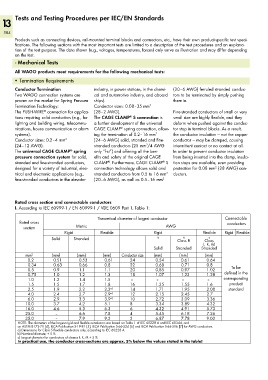
Rated cross section and connectable conductors
I. According to IEC 60999-1 / EN 60999-1 / VDE 0609 Part 1, Table 1:
Theoretical diameter of largest conductor Connectable
Rated cross conductors
section Metric AWG
Rigid Flexible Rigid Flexible Rigid Flexible
Solid Stranded b) b) c)
Class B Class
I, K, M
Solid Stranded Stranded
mm 2 (mm) (mm) (mm) Conductor size (mm) (mm) (mm)
0.2 0.51 0.53 0.61 24 0.54 0.61 0.64
0.34 0.63 0.66 0.8 22 0.68 0.71 0.8
0.5 0.9 1.1 1.1 20 0,85 0.97 1.02 To be
0.75 1.0 1.2 1.3 18 1.07 1.23 1.28 defined in the
1.0 1.2 1.4 1.5 – – – – corresponding
1.5 1.5 1.7 1.8 16 1.35 1.55 1.6 product
2.5 1.9 2.2 2.3 a) 14 1.71 1.95 2.08 standard
4.0 2.4 2.7 2.9 a) 12 2.15 2.45 2.7
6.0 2.9 3.3 3.9 a) 10 2.72 3.09 3.36
10.0 3.7 4.2 5.1 8 3.34 3.89 4.32
16.0 4.6 5.3 6.3 6 4.32 4.91 5.73
25.0 – 6.6 7.8 4 5.45 6.18 7.26
35.0 – 7.9 9.2 2 6.87 7.78 9.02
NOTE: The diameters of the largest rigid and flexible conductors are based on Table 1 of IEC 60228 A and IEC 60344, and
on ASTM B172-71 [4], IECA Publication S-19-81 [5], IECA Publication S-66-524 [6] and IECA Publication S-66-516 [7] for AWG conductors.
a) Dimensions for Class 5 flexible conductors only, according to IEC 60228 A.
b) Nominal diameter + 5 %
c) Largest diameter for conductors of classes I, K, M + 5 %
In practical use, the conductor cross-sections are approx. 5% below the values stated in the table!