
Page 587 - Wago_PCB_TerminalBlocksConnectors_Volume2_2015_US
P. 587
13
585
According to IEC 60999-1/EN 60999- For applications in special areas with One Conductor per Clamping Unit
1/VDE 0609 requirements for clamping extremely corrosive atmospheres, special A number of VDE specifications specify
units (Part 1, Section 7.1): conditions apply. that only one conductor must be
connected per clamping unit (e.g.,
In this case the use of solid copper wires DIN VDE 0611, Part 4, 02.91, Section
Clamping units must be able to or fine-stranded copper wires with prop- 3.1.9). The same applies to the recom-
clamp unprepared conductors. erly crimped, tinned copper ferrules or mendations of the German Automotive
copper pin terminals is recommended. Industry Association (VDA) “Supply
Under normal operating conditions, direct specification for the electrical equipment
clamping (i.e., direct conductor connec- As with solid copper conductors, the fine of machines, mechanical installations
tion to the current bar of the terminal strands are crimped to a dense inner and buildings in the automotive industry”
block) provides optimal contact quality core. This prevents ingress of the aggres- according to Section 15.1.1.3; Draft
since all risk factors arising from anti- sive atmosphere (depending on the ppm 8.93.
splaying methods are prevented. concentration), which can diffuse into the
conductor bundle along the individual Other VDE and EN specifications likewise
Occasionally, conductor anti-splaying strands and cause corrosion deposits recommend the connection of only one
protection may be required, including between individual strands and the conductor per clamping unit, unless
various methods (see illustrations below). clamping point. the clamping unit is specifically tested
and approved for the connection of sev-
II. According to IEC 60999-2 / EN 60999-2 / VDE 0609 Part 101, Table 1: eral conductors, for example:
VDE 0609, Part 1, 12.00/
Theoretical diameter of largest conductor Connectable EN 60999-1:2000, Paragraph 7.1
Rated Metric AWG/Kcmil conductors VDE 0660-600-1, 06.10/
cross EN61439-1: 2009, Paragraph 8.6.3
section Rigid VDE 0113, Part 1, 06.07/
Gage Rigid EN 60204-1:2006, Paragraph 13.1.1
Stranded Fine- Stranded Fine- This WAGO principle is the basis for a
stranded a) stranded number of other technical and economic
mm 2 (mm) (mm) (mm) (mm) Rigid Flexible advantages:
50 9.1 11 0 9.64 12.08 – Each conductor may be terminated or
70 11 13.1 00 11.17 13.54 removed without affecting previously con-
95 12.9 15.1 000 12.54 15.33 To be nected conductors.
– – – 0000 14.08 17.22 defined in the – Where re-wiring is required, only the
120 14.5 17 250 15.34 19.01 conductor to be changed is removed
150 16.2 19 300 16.8 20.48 corresponding from the clamping point, all other conduc-
185 18.0 21 350 18.16 22.05 product tors remain safely clamped.
– – – 400 19.42 24.05 standard
240 20.6 24 500 21.68 26.57
300 23.1 27 600 23.82 30.03 – Each conductor is clamped indepen-
a) Dimensions for class 5 flexible conductors only, according to IEC 60228A. dently.
NOTE: The diameters of the largest rigid and flexible conductors are based on Table 1 and Table 3 of IEC Any combination of conductor cross-
60228 A and, on ASTM B 172-71 [1], IECA Publication section can be connected.
S-19-81 [2], IECA Publication S-66-524 [3] and IECA Publication S-66-516 [7] for AWG conductors.
WAGO provides 2-conductor terminal
blocks and connectors to increase the
number of clamping units.
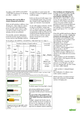
Tip-bonded conductor Tin-plated copper ferrule (gas-tight, crimped)
Anti-splaying methods require a terminal
block one size larger than the nominal
cross-section of the conductor to be terminat-
ed.
Ultrasonically bonded con- The cross section values assigned to the
ductor individual products with ferrules are based
on the WAGO Variocrimp method from all
sides. 13
Gas-tight, crimped twin ferrules may be
used, provided the ferrule is inserted all
the way into the clamping unit and that
Crimped pin terminals (gas-tight), prefer- there is a sufficient clearance and creep-
ably made of copper with a tin-plated age distance between adjacent potentials.
surface