
Page 21 - Paker - Medium Duty Hydraulic Cylinders
P. 21
Catalog HY08-1130-4/NA Medium Duty Hydraulic Cylinders
Piston Rod Ends – 1.00" to 5.00" Bore Series 3L
Rod End Dimensions
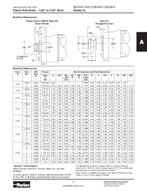
Thread Style 9 (NFPA Style SF) Style 55 1
2
Small Female Flanged Rod End
WF WG
A V
W .06R
V
A
ØB ØAM Ø MM
ØB KK Ø MM
ØAF
D WRENCH AE
FLATS
NA AD F
F
Rod End Dimensions
Bore Rod MM Thread A B Ø D F NA V W WF Bore Rod MM Thread Rod Extensions and Pilot Dimensions
Ø No. Rod +.000 Ø No. Rod
Ø Style Style -.002 Ø Style A AD AE AF AM B Ø D F NA V W WF WG
8 4 9 +.001 Ø Ø +.000
CC KK KK -.001 -.002
1 (Std.) 0.500 7/16-20 5/16-24 0.63 0.999 0.38 0.38 0.44 0.25 0.63 1.00 1 (Std.) 0.500 5/16-24 0.63 – – – – 0.999 0.38 0.38 0.44 0.25 0.63 1.00 –
1.00 1.00
2 0.625 1/2-20 7/16-20 0.75 1.124 0.50 0.38 0.56 0.25 0.63 1.00 2 0.625 7/16-20 0.75 0.63 0.25 0.38 0.57 1.124 0.50 0.38 0.56 0.25 0.63 1.00 1.75
1 (Std.) 0.625 1/2-20 7/16-20 0.75 1.124 0.50 0.38 0.56 0.25 0.63 1.00 1 (Std.) 0.625 7/16-20 0.75 0.63 0.25 0.38 0.57 1.124 0.50 0.38 0.56 0.25 0.63 1.00 1.75
1.50 1.50
2 1.000 7/8-14 3/4-16 1.13 1.499 0.88 0.38 0.94 0.50 1.00 1.38 2 1.000 3/4-16 1.13 0.94 0.38 0.69 0.95 1.499 0.88 0.38 0.94 0.50 1.00 1.38 2.38
1 (Std.) 0.625 1/2-20 7/16-20 0.75 1.124 0.50 0.38 0.56 0.25 0.63 1.00 1 (Std.) 0.625 7/16-20 0.75 0.63 0.25 0.38 0.57 1.124 0.50 0.38 0.56 0.25 0.63 1.00 1.75
2.00 2 1.375 1 1/4-12 1-14 1.63 1.999 1.13 0.38 1.31 0.63 1.25 1.63 2.00 2 1.375 1-14 1.63 1.06 0.38 0.88 1.32 1.999 1.13 0.38 1.31 0.63 1.25 1.63 2.75
3 1.000 7/8-14 3/4-16 1.13 1.499 0.88 0.38 0.94 0.50 1.00 1.38 3 1.000 3/4-16 1.13 0.94 0.38 0.69 0.95 1.499 0.88 0.38 0.94 0.50 1.00 1.38 2.38
1 (Std.) 1.000 7/8-14 3/4-16 1.13 1.499 0.88 0.38 0.94 0.50 1.00 1.38 1 (Std.) 1.000 3/4-16 1.13 0.94 0.38 0.69 0.95 1.499 0.88 0.38 0.94 0.50 1.00 1.38 2.38
2 1.750 1 1/2-12 1 1/4-12 2.00 2.374 1.50 0.38 1.69 0.75 1.50 1.88 2 1.750 1 1/4-12 2.00 1.31 0.50 1.13 1.70 2.374 1.50 0.38 1.69 0.75 1.50 1.88 3.13
2.50 2.50
3 1.375 1 1/4-12 1-14 1.63 1.999 1.13 0.38 1.31 0.63 1.25 1.63 3 1.375 1-14 1.63 1.06 0.38 0.88 1.32 1.999 1.13 0.38 1.31 0.63 1.25 1.63 2.75
7 0.625 1/2-20 7/16-20 0.75 1.124 0.50 0.38 0.56 0.25 0.63 1.00 7 0.625 7/16-20 0.75 0.63 0.25 0.38 0.57 1.124 0.50 0.38 0.56 0.25 0.63 1.00 1.75
1 (Std.) 1.000 7/8-14 3/4-16 1.13 1.499 0.88 0.63 0.94 0.25 0.75 1.38 1 (Std.) 1.000 3/4-16 1.13 0.94 0.38 0.69 0.95 1.499 0.88 0.63 0.94 0.25 0.75 1.38 2.38
2 2.000 1 3/4-12 1 1/2-12 2.25 2.624 1.69 0.63 1.94 0.50 1.38 2.00 2 2.000 1 1/2-12 2.25 1.69 0.63 1.38 1.95 2.624 1.69 0.63 1.94 0.50 1.38 2.00 3.75
3.25 3.25
3 1.375 1 1/4-12 1-14 1.63 1.999 1.13 0.63 1.31 0.38 1.00 1.63 3 1.375 1-14 1.63 1.06 0.38 0.88 1.32 1.999 1.13 0.63 1.31 0.38 1.00 1.63 2.75
4 1.750 1 1/2-12 1 1/4-12 2.00 2.374 1.50 0.63 1.69 0.50 1.25 1.88 4 1.750 1 1/4-12 2.00 1.31 0.50 1.13 1.70 2.374 1.50 0.63 1.69 0.50 1.25 1.88 3.13
1 (Std.) 1.375 1 1/4-12 1-14 1.63 1.999 1.13 0.63 1.31 0.38 1.00 1.63 1 (Std.) 1.375 1-14 1.63 1.06 0.38 0.88 1.32 1.999 1.13 0.63 1.31 0.38 1.00 1.63 2.75
2 2.500 2 1/4-12 1 7/8-12 3.00 3.124 2.06 0.63 2.38 0.63 1.63 2.25 2 2.500 1 7/8-12 3.00 1.94 0.75 1.75 2.45 3.124 2.06 0.63 2.38 0.63 1.63 2.25 4.50
4.00 3 1.750 1 1/2-12 1 1/4-12 2.00 2.374 1.50 0.63 1.69 0.50 1.25 1.88 4.00 3 1.750 1 1/4-12 2.00 1.31 0.50 1.13 1.70 2.374 1.50 0.63 1.69 0.50 1.25 1.88 3.13
4 2.000 1 3/4-12 1 1/2-12 2.25 2.624 1.69 0.63 1.94 0.50 1.38 2.00 4 2.000 1 1/2-12 2.25 1.69 0.63 1.38 1.95 2.624 1.69 0.63 1.94 0.50 1.38 2.00 3.75
7 1.000 7/8-14 3/4-16 1.13 1.499 0.88 0.63 0.94 0.25 0.75 1.38 7 1.000 3/4-16 1.13 0.94 0.38 0.69 0.95 1.499 0.88 0.63 0.94 0.25 0.75 1.38 2.38
1 (Std.) 1.750 1 1/2-12 1 1/4-12 2.00 2.374 1.50 0.63 1.69 0.50 1.25 1.88 1 (Std.) 1.750 1 1/4-12 2.00 1.31 0.50 1.13 1.70 2.374 1.50 0.63 1.69 0.50 1.25 1.88 3.13
2 3.500 3 1/4-12 2 1/2-12 3.50 4.249 3.00 0.63 3.38 0.63 1.63 2.25 2 3.500 2 1/2-12 3.50 2.69 1.00 2.50 3.45 4.249 3.00 0.63 3.38 0.63 1.63 2.25 5.63
3 2.000 1 3/4-12 1 1/2-12 2.25 2.624 1.69 0.63 1.94 0.50 1.38 2.00 3 2.000 1 1/2-12 2.25 1.69 0.63 1.38 1.95 2.624 1.69 0.63 1.94 0.50 1.38 2.00 3.75
5.00 4 2.500 2 1/4-12 1 7/8-12 3.00 3.124 2.06 0.63 2.38 0.63 1.63 2.25 5.00 4 2.500 1 7/8-12 3.00 1.94 0.75 1.75 2.45 3.124 2.06 0.63 2.38 0.63 1.63 2.25 4.50
5 3.000 2 3/4-12 2 1/4-12 3.50 3.749 2.63 0.63 2.88 0.63 1.63 2.25 5 3.000 2 1/4-12 3.50 2.44 0.88 2.25 2.95 3.749 2.63 0.63 2.88 0.63 1.63 2.25 4.88
7 1.000 7/8-14 3/4-16 1.13 1.499 0.88 0.63 0.94 0.25 0.75 1.38 7 1.000 3/4-16 1.13 0.94 0.38 0.69 0.95 1.499 0.88 0.63 0.94 0.25 0.75 1.38 2.38
8 1.375 1 1/4-12 1-14 1.63 1.999 1.13 0.63 1.31 0.38 1.00 1.63 8 1.375 1-14 1.63 1.06 0.38 0.88 1.32 1.999 1.13 0.63 1.31 0.38 1.00 1.63 2.75
“Special” Thread Style 3 1 For special WG dimension, specify “Style 3” and give desired
Special thread, extension, rod eye, blank, etc., are also dimension for WG. For other changes, place “S” in the model code,
available. and describe rod end with dimensioned sketch.
2 Style 9 stroke restrictions may apply. See Style 9 Minimum Stroke
To order, specify “Style 3” and give desired dimensions for KK, Table on How to Order page for details.
A, W or WF. If otherwise special, furnish dimensioned sketch.
11 Parker Hannifin Corporation
11
Industrial Cylinder Division
www.parker.com/cylinder Des Plaines, Illinois