Page 23 - Paker - Medium Duty Hydraulic Cylinders
P. 23

Catalog HY08-1130-4/NA                            Medium Duty Hydraulic Cylinders
            Mounting Information – 1.00" to 6.00" Bore        Series 3L


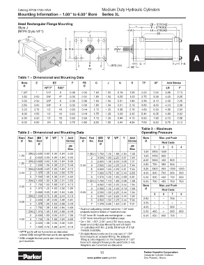
            Head Rectangular Flange Mounting                                               ZB + STROKE
            Style J                                                               Y         P + STROKE
            (NFPA Style MF1)                          UF                       W           LB + STROKE
                                                       1                                       EE


                                        E  R  4                   2   ØMM
                                                                                                                     A

                                                      3                          F   G                    J    K
                                                      E             ØFB (X4)   WF
                                                      TF

            Table 1 – Dimensional and Mounting Data
              Bore     E         EE         F      FB     G       J      K      R     TF      UF     Add Stroke
               Ø                                   Ø
                            NPTF 1   SAE 2                                                           LB     P
              1.00 3   4     1/4 5   6     0.38   0.25   1.50   1.00    0.19   1.08   2.00   2.50   3.88   2.13
              1.50    2.00   3/8 5   6 6   0.38   0.31   1.50   1.00    0.25   1.43   2.75   3.38   4.00   2.25
              2.00    2.50   3/8 5   6     0.38   0.38   1.50   1.00    0.31   1.84   3.38   4.13   4.00   2.25
              2.50    3.00   3/8 5   6     0.38   0.38   1.50   1.00    0.31   2.19   3.88   4.63   4.13   2.38
              3.25    3.75   1/2    10     0.63   0.44   1.75   1.25    0.38   2.76   4.69   5.50   4.88   2.63
              4.00    4.50   1/2    10     0.63   0.44   1.75   1.25    0.38   3.32   5.44   6.25   4.88   2.63
              5.00   5.50    1/2    10     0.63   0.56   1.75   1.25    0.44   4.10   6.63   7.63   5.13   2.88
              6.00   6.50     3/4   12     0.75   0.56   2.00   1.50    0.44   4.88   7.63   8.63   5.75   3.13
                                                                                      Table 3 – Maximum
            Table 2 – Dimensional and Mounting Data                                   Operating Pressure
            Bore  Rod   MM   W  WF    Y   Add    Bore  Rod   MM   W   WF   Y   Add     Bore            Max. psi Push
              Ø   No.  Rod               Stroke   Ø    No.  Rod               Stroke    Ø
                        Ø                                    Ø                                    Rod Code
                                          ZB                                   ZB            1     2    3    4
                                          Max                                  Max
                                                                                       1.00  1900  1500  –   –
                 1 (Std.) 0.500 0.63 1.00 1.94  5.00  1 (Std.) 1.750 1.25 1.88 2.94  7.06
             1.00                                                                      1.50  1400  850  –    –
                   2   0.625 0.63 1.00 1.94  5.00       2  3.500 1.63 2.25 3.31  7.44
                 1 (Std.) 0.625 0.63 1.00 1.94  5.06    3  2.000 1.38 2.00 3.06  7.31  2.00  1050  450  800  –
             1.50                                                                      2.50  700  350  500   –
                   2   1.000 1.00 1.38 2.31  5.44  5.00  4  2.500 1.63 2.25 3.31  7.44
                 1 (Std.) 0.625 0.63 1.00 1.94  5.13    5  3.000 1.63 2.25 3.31  7.44  3.25  1300  900  1300  1000
             2.00  2   1.375 1.25 1.63 2.56  5.75       7  1.000 0.75 1.38 2.44  6.56  4.00  900  700  900   900
                   3   1.000 1.00 1.38 2.31  5.50       8  1.375 1.00 1.63 2.69  6.81  5.00  600  400  700   600
                 1 (Std.) 1.000 1.00 1.38 2.31  5.63  1 (Std.) 1.750 1.13 1.88 3.06  7.56  6.00  700  450  700  700
                   2   1.750 1.50 1.88 2.81  6.13       2  4.000 1.50 2.25 3.44  7.94
             2.50                                                                      Bore            Max. psi Push
                   3   1.375 1.25 1.63 2.56  5.88       3  2.000 1.25 2.00 3.19  7.69   Ø         Rod Code
                   7   0.625 0.63 1.00 1.94  5.25  6.00  4  2.500 1.50 2.25 3.44  7.94
                 1 (Std.) 1.000 0.75 1.38 2.44  6.19    5  3.000 1.50 2.25 3.44  7.94        5     6    7    8
                   2   2.000 1.38 2.00 3.06  6.81       6  3.500 1.50 2.25 3.44  7.94  2.50  –     –   700   –
             3.25                                                                      3.25  –     –    –    –
                   3   1.375 1.00 1.63 2.69  6.44       7  1.375 0.88 1.63 2.81  7.31
                   4   1.750 1.25 1.88 2.94  6.69  3  Cushion adjusting needle valve for 1.00" bore   4.00  –  –  900  –
                 1 (Std.) 1.375 1.00 1.63 2.69  6.44  projects beyond sides of head and cap.  5.00  450  –  600  800
                   2   2.500 1.63 2.25 3.31  7.06  4  1.00" bore 3L heads are rectangular — see   6.00  650  600  700  –
             4.00  3   1.750 1.25 1.88 2.94  6.69  1.00" bore mounting information page.
                                                5  On 1.00", 1.50", 2.00" and 2.50" bore sizes, the
                   4   2.000 1.38 2.00 3.06  6.81  head end (only) pipe thread is not full depth
                   7   1.000 0.75 1.38 2.44  6.19  on cylinders with No. 2 rods. Minimum of 3 full
                                                 threads available.
            1  NPTF ports will be furnished as standard   6
             unless SAE straight thread ports are specified.   Straight thread ports on the cap end of 1.50"
            2  SAE straight thread ports are indicated by   bore require an adapter fitting. An adapter
                                                 fitting is also required on the head end of 1.50"
             port number.                        bore with straight thread ports and Code 2 rod.
                                                 Adapters are furnished as standard.

                                                             13                        Parker Hannifin Corporation
                                                             13
                                                                                       Industrial Cylinder Division
                                                     www.parker.com/cylinder           Des Plaines, Illinois
   18   19   20   21   22   23   24   25   26   27   28