
Page 28 - Paker - Medium Duty Hydraulic Cylinders
P. 28
Catalog HY08-1130-4/NA Medium Duty Hydraulic Cylinders
Mounting Information – 1.00" to 5.00" Bore Series 3L
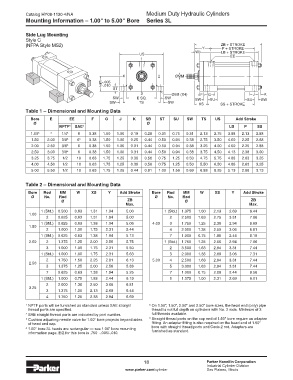
Side Lug Mounting
Style C
(NFPA Style MS2) Y ZB + STROKE
P + STROKE
W LB + STROKE
US EE
1
4 2 ØMM
E -.005
2 -.010
ST
3 ØSB (X4) F G J K
SW E SQ. SW SW SU SU SW
SW TS SW XS SS + STROKE
Table 1 – Dimensional and Mounting Data
Bore E EE F G J K SB ST SU SW TS US Add Stroke
Ø Ø
NPTF 1 SAE 2 LB P SS
1.00 3 4 1/4 5 6 0.38 1.50 1.00 0.19 0.28 0.31 0.75 0.31 2.13 2.75 3.88 2.13 2.88
1.50 2.00 3/8 5 6 6 0.38 1.50 1.00 0.25 0.44 0.50 0.94 0.38 2.75 3.50 4.00 2.25 2.88
2.00 2.50 3/8 5 6 0.38 1.50 1.00 0.31 0.44 0.50 0.94 0.38 3.25 4.00 4.00 2.25 2.88
2.50 3.00 3/8 5 6 0.38 1.50 1.00 0.31 0.44 0.50 0.94 0.38 3.75 4.50 4.13 2.38 3.00
3.25 3.75 1/2 10 0.63 1.75 1.25 0.38 0.56 0.75 1.25 0.50 4.75 5.75 4.88 2.63 3.25
4.00 4.50 1/2 10 0.63 1.75 1.25 0.38 0.56 0.75 1.25 0.50 5.50 6.50 4.88 2.63 3.25
5.00 5.50 1/2 10 0.63 1.75 1.25 0.44 0.81 1.00 1.56 0.69 6.88 8.25 5.13 2.88 3.13
Table 2 – Dimensional and Mounting Data
Bore Rod MM W XS Y Add Stroke Bore Rod MM W XS Y Add Stroke
Ø No. Rod Ø No. Rod
Ø ZB Ø ZB
Max. Max.
1 (Std.) 0.500 0.63 1.31 1.94 5.00 1 (Std.) 1.375 1.00 2.13 2.69 6.44
1.00
2 0.625 0.63 1.31 1.94 5.00 2 2.500 1.63 2.75 3.31 7.06
1 (Std.) 0.625 0.63 1.38 1.94 5.06 4.00 3 1.750 1.25 2.38 2.94 6.69
1.50
2 1.000 1.00 1.75 2.31 5.44 4 2.000 1.38 2.50 3.06 6.81
1 (Std.) 0.625 0.63 1.38 1.94 5.13 7 1.000 0.75 1.88 2.44 6.19
2.00 2 1.375 1.25 2.00 2.56 5.75 1 (Std.) 1.750 1.25 2.56 2.94 7.06
3 1.000 1.00 1.75 2.31 5.50 2 3.500 1.63 2.94 3.31 7.44
1 (Std.) 1.000 1.00 1.75 2.31 5.63 3 2.000 1.38 2.69 3.06 7.31
2 1.750 1.50 2.25 2.81 6.13 5.00 4 2.500 1.63 2.94 3.31 7.44
2.50
3 1.375 1.25 2.00 2.56 5.88 5 3.000 1.63 2.94 3.31 7.44
7 0.625 0.63 1.38 1.94 5.25 7 1.000 0.75 2.06 2.44 6.56
1 (Std.) 1.000 0.75 1.88 2.44 6.19 8 1.375 1.00 2.31 2.69 6.81
2 2.000 1.38 2.50 3.06 6.81
3.25
3 1.375 1.00 2.13 2.69 6.44
4 1.750 1.25 2.38 2.94 6.69
1 NPTF ports will be furnished as standard unless SAE straight 5 On 1.00", 1.50", 2.00" and 2.50" bore sizes, the head end (only) pipe
thread ports are specified. thread is not full depth on cylinders with No. 2 rods. Minimum of 3
2 SAE straight thread ports are indicated by port number. full threads available.
3 Cushion adjusting needle valve for 1.00" bore projects beyond sides 6 Straight thread ports on the cap end of 1.50" bore require an adapter
of head and cap. fitting. An adapter fitting is also required on the head end of 1.50"
4 1.00" bore 3L heads are rectangular — see 1.00" bore mounting bore with straight thread ports and Code 2 rod. Adapters are
information page. E/2 for this bore is .750 -.005/-.010. furnished as standard.
18 Parker Hannifin Corporation
Industrial Cylinder Division
www.parker.com/cylinder Des Plaines, Illinois