Page 25 - Paker - Medium Duty Hydraulic Cylinders
P. 25

Catalog HY08-1130-4/NA                            Medium Duty Hydraulic Cylinders
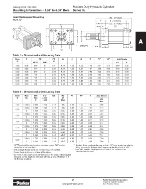
            Mounting Information – 1.50" to 6.00" Bore        Series 3L


            Head Rectangular Mounting                                                        ZB + STROKE
            Style JJ 3
                                                                                     Y       P + STROKE
                                                                                   WF        LG + STROKE
                                                    UF
                                                    1                             RT             EE


                                       E 4                     2  R  ØRD ØMM           ØB
                                                                                                                     A


                                                    3               ØFB (X4)     KB      G                J    K
                                                    E
                                                    TF
            Table 1 – Dimensional and Mounting Data
              Bore     E          EE         FB      G       J       K      R      TF      UF      Add Stroke
               Ø                              Ø
                             NPTF 1   SAE 2                                                        LG      P
              1.50    2.00    3/8 4   6 5    0.31   1.50    1.00    0.25   1.43    2.31   2.75    3.63    2.25
              2.00    2.50    3/8 4   6      0.38   1.50    1.00    0.31   1.84    2.88   3.38    3.63    2.25
              2.50    3.00    3/8 4   6      0.38   1.50    1.00    0.31   2.19    3.25   3.75    3.75    2.38
              3.25    3.75    1/2     10     0.44   1.75    1.25    0.38   2.76    4.00   4.63    4.25    2.63
              4.00    4.50    1/2     10     0.44   1.75    1.25    0.38   3.32    4.50   5.13    4.25    2.63
              5.00    5.50    1/2     10     0.56   1.75    1.25    0.44   4.10    5.63   6.44    4.50    2.88
              6.00    6.50    3/4     12     0.56   2.00    1.50    0.44   4.88    6.44   7.25    5.00    3.13


            Table 2 – Dimensional and Mounting Data

              Bore    Rod     MM     B Ø     KB      RD     RT      WF      Y     Add Stroke
               Ø      No.    Rod     +.000           Ø
                              Ø      -.002          Max                              ZB
                                                                                     Max
              1.50   1 (Std.)  0.625  1.124  0.19   1.967   0.25    1.00   1.94      5.06
                     1 (Std.)  0.625  1.124  0.19   1.967   0.25    1.00   1.94      5.13
              2.00
                       3     1.000   1.499   0.25   2.467   0.38    1.38   2.31      5.50
                     1 (Std.)  1.000  1.499  0.25   2.467   0.38    1.38   2.31      5.63
              2.50
                       3     1.375   1.999   0.25   2.967   0.38    1.63   2.56      5.88
                     1 (Std.)  1.000  1.499  0.25   2.467   0.38    1.38   2.44      6.19
              3.25
                       3     1.375   1.999   0.25   2.967   0.38    1.63   2.69      6.44
                     1 (Std.)  1.375  1.999  0.25   2.967   0.38    1.63   2.69      6.44
              4.00
                       3     1.750   2.374   0.25   3.467   0.38    1.88   2.94      6.69
                     1 (Std.)  1.750  2.374  0.25   3.467   0.38    1.88   2.94      7.06
              5.00
                       3     2.000   2.624   0.25   3.717   0.38    2.00   3.06      7.31
                     1 (Std.)  1.750  2.374  0.25   3.467   0.38    1.88   3.06      7.56
              6.00
                       3     2.000   2.624   0.25   3.717   0.38    2.00   3.19      7.69
            1  NPTF ports will be furnished as standard unless SAE straight    5  Straight thread ports on the cap end of 1.50" bore require an adapter
              thread ports are specified.                        fitting. An adapter fitting is also required on the head end of 1.50"
            2  SAE straight thread ports are indicated by port number.    bore with straight thread ports and Code 2 rod. Adapters are
            3  Parker Style JJ Mount is a Non-NFPA Mount.        furnished as standard.
            4  On 1.00", 1.50", 2.00" and 2.50" bore sizes, the head end (only) pipe
              thread is not full depth on cylinders with No. 2 rods. Minimum of 3
              full threads available.


                                                             15                        Parker Hannifin Corporation
                                                             15
                                                                                       Industrial Cylinder Division
                                                     www.parker.com/cylinder           Des Plaines, Illinois
   20   21   22   23   24   25   26   27   28   29   30