
Page 223 - Parker - Parker Pneumatic
P. 223
Catalog PDN1000-3US Actuator Products – Rodless Cylinders
Parker Pneumatic OSP-P Series – Sizing
intermediate supports
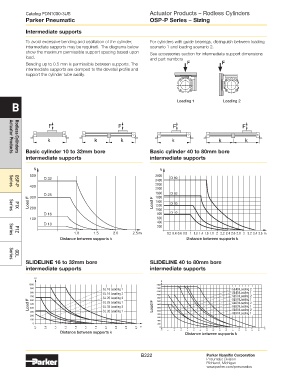
To avoid excessive bending and oscillation of the cylinder, For cylinders with guide bearings, distinguish between loading
intermediate supports may be required. The diagrams below scenario 1 and loading scenario 2.
show the maximum permissible support spacing based upon See accessories section for intermediate support dimensions
load. and part numbers
Bending up to 0.5 mm is permissible between supports. The
intermediate supports are clamped to the dovetail profile and
support the cylinder tube axially.
B Loading 1 Loading 2
Basic cylinder 10 to 32mm bore Basic cylinder 40 to 80mm bore
Actuator Products
Rodless Cylinders
intermediate supports intermediate supports
N N
500 2600
D 32 2400 D 80
2200
400
2000
Series
OSP-P
D 25 1800 D 63
300
1600
Load F 200 Load F 1400 D 50
1200
P1X
Series
800
D 16 1000 D 40
100 600
D 10 400
200
1.0 1.5 2.0 2.5 m 0.2 0.4 0.6 0.8 1 1.2 1.4 1.6 1.8 2 2.2 2.4 2.6 2.8 3 3.2 3.4 3.6 m
P1Z
Series
Distance between supports k Distance between supports k
GDL
SliDeliNe 16 to 32mm bore SliDeliNe 40 to 80mm bore
Series
intermediate supports intermediate supports
SL 16 Loading 1 SL40 Loading 2
SL 16 Loading 2 SL40 Loading 1
SL 25 Loading 2 SL50 Loading 2
SL50 Loading 1
Load F SL 25 Loading 1 Load F SL63 Loading 2
SL63 Loading 1
SL 32 Loading 2
SL80 Loading 2
SL 32 Loading 1
SL80 Loading 1
Distance between supports k Distance between supports k
B222 Parker Hannifin Corporation
Pneumatic Division
Richland, Michigan
www.parker.com/pneumatics