
Page 221 - Parker - Parker Pneumatic
P. 221
Catalog PDN1000-3US Actuator Products – Rodless Cylinders
Parker Pneumatic OSP-P Series – Sizing
loads, forces and moments
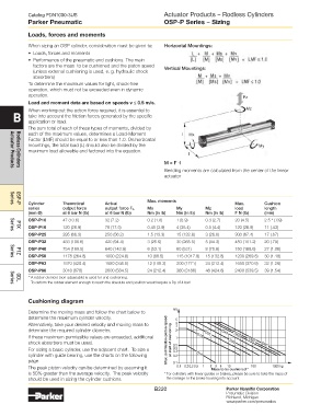
When sizing an OSP cylinder, consideration must be given to: Horizontal Mountings:
• Loads, forces and moments
• Performance of the pneumatic end cushions. The main
factors are the mass to be cushioned and the piston speed
(unless external cushioning is used, e. g. hydraulic shock Vertical Mountings:
absorbers)
To determine the maximum values for light, shock-free
operation, which must not be exceeded even in dynamic
operation. Fz
load and moment data are based on speeds v ≤ 0.5 m/s. Mz
B When working out the action force required, it is essential to
take into account the friction forces generated by the specific
application or load.
The sum total of each of these types of moments, divided by
each of the maximum values, determines a Load-Moment I Mx
Factor (LMF) should be equal to or less than 1.0. On horizontal
mountings, the total load (L) should also be divided by the My
maximum load allowable and factored into the equation.
I
M = F ·l
Bending moments are calculated from the center of the linear
Actuator Products
Rodless Cylinders
actuator
Max. moments
Cylinder Theoretical Actual Max. Cushion
Series
series output force output force F A Mx My Mz load length
OSP-P
(mm Ø) at 6 bar N (lb) at 6 bar N (lb) Nm (in lb) Nm (in lb) Nm (in lb) F N (lb) (mm)
OSP-P10 47 (10.6) 32 (7.2) 0.2 (1.8) 1 (8.9) 0.3 (2.7) 20 (4.5) 2.5 * (.09)
OSP-P16 120 (26.9) 78 (17.5) 0.45 (3.9) 4 (35.4) 0.5 (4.4) 120 (26.9) 11 (.43)
P1X
Series
OSP-P25 295 (66.3) 250 (56.2) 1.5 (13.3) 15 (132.8) 3 (26.6) 300 (67.4) 17 (.67)
OSP-P32 483 (108.6) 420 (94.4) 3 (26.6) 30 (265.5) 5 (44.3) 450 (101.2) 20 (.79)
OSP-P40 754 (169.5) 640 (143.9) 6 (53.1) 60 (531) 8 (70.8) 750 (168.6) 27 (1.06)
OSP-P50 1178 (264.8) 1000 (224.8) 10 (88.5) 115 (1017.8) 15 (132.8) 1200 (269.8) 30 (1.18)
P1Z
Series
OSP-P63 1870 (420.4) 1550 (348.5) 12 (106.2) 200 (1771) 24 (212.4) 1650 (370.9) 32 (1.26)
OSP-P80 3016 (678) 2600 (584.5) 24 (212.4) 360 (3186) 48 (424.8) 2400 (539.5) 39 (1.54)
* A rubber element (non-adjustable) is used for end cushioning.
To deform the rubber element enough to reach the absolute end position would require a Dp of 4 bar!
GDL
Series
Cushioning diagram
m/s
Determine the moving mass and follow the chart below to
determine the maximum cylinder velocity. 5
Alternatively, take your desired velocity and moving mass to 4 3
determine the required cylinder diameter. 2
If these maximum permissible values are exceeded, additional 1
shock absorbers must be used. Max. permissible piston speed at start of cushioning 0.5
For sizing a basic cylinder, use the adjacent chart. To size a 0.4
0.3
cylinder with guide bearing, use the charts on the following 0.2
page. 0.1
The peak piston velocity can be determined by assuming it 0.1 0.20.3 0.5 1 2 3 5 10 100 1000 kg
Mass to be cushioned *
is 50% greater than the average velocity. The peak velocity * For cylinders with linear guides or brakes, please be sure to take the mass of
should be used in sizing the cylinder cushions. the carriage or the brake housing into account.
B220 Parker Hannifin Corporation
Pneumatic Division
Richland, Michigan
www.parker.com/pneumatics