Page 222 - Parker - Parker Pneumatic
P. 222

Catalog PDN1000-3US                                 Actuator Products – Rodless Cylinders
            Parker Pneumatic                                    OSP-P Series – Sizing

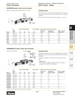
            SliDeliNe loads, forces and moments

            Stroke up to 5500 mm (longer strokes on request)    technical data
                                                                The table shows the maximum permissible values for smooth
                                                                operation, which should not be exceeded even under dynamic
                                                                conditions.
                                                                The load and moment figures apply to speeds v < 0.2 m/s.


                                                                                                                   B

                                 Max. moments (Nm)    Max. loads (N)  Mass of linear drive with guide (kg)
                      For
                      linear                                       With 0mm    Increase per     Mass * of guide
            Series    drive      Mx     My     Mz     Fy, Fz       stroke      100mm stroke     carriage (kg)
            SL16      OSP-P16    6      11     11     325          0.57        0.22             0.23
            SL25      OSP-P25    14     34     34     675          1.55        0.39             0.61                 Rodless Cylinders   Actuator Products
            SL32      OSP-P32    29     60     60     925          2.98        0.65             0.95
            SL40      OSP-P40    50     110    110    1500         4.05        0.78             1.22
            SL50      OSP-P50    77     180    180    2000         6.72        0.97             2.06
            SL63      OSP-P63    120    260    260    2500         11.66       1.47             3.32
            SL80      OSP-P80    120    260    260    2500         15.71       1.81             3.32
            * Add the mass of the guide carriage to the mass to be cushioned.
                                                                                                                     OSP-P   Series

            POWerSliDe loads, forces and moments

            Stroke up to 3500 mm       Example: PS 25/35        technical data
                                                     width of   The table shows the maximum permissible values for smooth   P1X   Series
                                                     guide rail
                                                     (35 mm)    operation, which should not be exceeded even under dynamic
                                                                conditions.
                                                     size of drive
                                                     OSP-P25    For further information and technical data see linear drives
                                                                OSP-P.                                               P1Z   Series
                                                                * Please note:
                                                                 In the cushioning diagram, add the  mass of the guide
                                                                 carriage to the mass to be cushioned.
                                                                                                                     GDL   Series


                                 Max. moments (Nm)    Max. load (N)  Mass of linear drive with guide (kg)
                      For
                      linear                                       With 0 mm   Increase per    Mass * of guide
            Series    drive      Mx     My     Mz     Fy, Fz       stroke      100mm  stroke   carriage (kg)
            PS 16/25  OSP-P16    14     45     45     1400         0.93        0.24            0.7
            PS 25/25  OSP-P25    14     63     63     1400         1.5         0.4             0.7
            PS 25/35  OSP-P25    20     70     70     1400         1.7         0.4             0.8
            PS 25/44  OSP-P25    65     175    175    3000         2.6         0.5             1.5
            PS 32/35  OSP-P32    20     70     70     1400         2.6         0.6             0.8
            PS 32/44  OSP-P32    65     175    175    3000         3.4         0.7             1.5
            PS 40/44  OSP-P40    65     175    175    3000         4.6         1.1             1.5
            PS 40/60  OSP-P40    90     250    250    3000         6           1.3             2.2
            PS 50/60  OSP-P50    90     250    250    3000         7.6         1.4             2.3
            PS 50/76  OSP-P50    140    350    350    4000         11.5        1.8             4.9
            * Add the mass of the guide carriage to the mass to be cushioned.
                                                            B221                       Parker Hannifin Corporation
                                                                                       Pneumatic Division
                                                                                       Richland, Michigan
                                                                                       www.parker.com/pneumatics
   217   218   219   220   221   222   223   224   225   226   227