
Page 345 - Parker - Parker Pneumatic
P. 345
Catalog PDN1000-3US Electronic Sensors
Parker Pneumatic Drop-in Reed Sensors
P8S Global Drop-In Reed Sensors
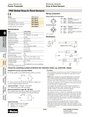
Wiring connection
Wiring Reed sensor Flying Lead or 8 mm Connector
4 Pin Wire Function
3m flying leads P8S-GRFLX 1 Brown Operating voltage (+V)
10m flying leads P8S-GRFTX 1 3 4 Black Not used
0.3m lead with 8mm connector P8S-GRSHX 3 Blue Output signal (-V or ground)
0.3m lead with 12mm connector P8S-GRMHX 12 mm Connector
1m lead with 8mm connector P8S-GRSCX 2* Pin Wire Function
1 Brown Operating voltage (+V)
Specifications 3 1 2* White Not used
B Type 2-Wire Reed 4 3 4 Blue Output signal (-V or ground)
Not used
Black
Output function
Normally open
Operating voltage 10 - 120 VAC*, 10 - 30 VDC * Pin 2 not present.
Switching power 6 W/VA Dimensions
Continuous current 100 mA max.
.17
Response sensitivity 30 Gauss min. (4.3)
Switching frequency 400 Hz 4.3
Voltage drop 2.5 V max.
.24 Sensing Face Center
Ripple 10% of operating voltage (6.1) .55
Hysteresis 1.5 mm max. (14)
Actuator Products
Electronic Sensors
Repeatability 0.2 mm max.
Emc EN 60 947-5-2
Reverse polarity protection Yes
Enclosure rating IP 68 1.24
L = 300
Shock and vibration stress 30g, 11 ms, 10 to 55 Hz, 1 mm (31.5)
Guide
Operating temperature range -25°C to +75°C (-13°F to 167°F) M8x1
Selection
Housing material PA 12, Black
Connector cable PVC
Connector PUR cable with 8 or 12 mm connector .1.42
(36)
* 8mm connector rated for 50 vac max.
Sensors
Drop-in
Circuit for switching contact protection (for inductive loads, e.g. solenoids, relays)
!
(Required for proper operation 24VDC) Caution
Put diode parallel to load (CR) following polarity as shown. – Use an ampmeter to test reed sensor current. Testing devices such
as incandescent light bulbs may subject the reed sensor to high
(BROWN) (BLUE) in-rush loads.
+
Solid State /
Reed Sensors
– NOTE: When checking an unpowered reed sensor for continuity
24VDC D CR with a digital ohmmeter the resistance reading will change from
– infinity to a very large resistance (2 M ohm) when the sensor is
activated. This is due to the presence of a diode in the reed sensor.
D: Diode: select a diode with the breakdown voltage and – Anti-magnetic shielding is recommended for reed sensors exposed
current rating according to the load. to high external RF or magnetic fields.
Sensors
Weld Immune
Typical Example – 100 volt, 1 amp diode – The magnetic field strength of the piston magnet is designed to
CR: Relay coil (under 0.5W coil rating) operate with our sensors. Other manufacturers’ sensors may not
operate correctly in conjunction with these magnets.
(Recommended for longer life 120 VAC)
Put a resistor and capacitor in parallel with the load (CR). – Use relay coils for reed sensor contact protection.
Select the resistor and capacitor according to the load. – The operation of some 120 VAC PLC’s (especially some older Allen-
Cordset /
Bradley PLC’s) can overload the reed sensor. The sensor may fail to
Connect Block
+ (BROWN) (BLUE) release after the piston magnet has passed. This problem may be
corrected by the placement of a 700 to 1K OHM resistor between
R
120VAC CR the sensor and the PLC input terminal. Consult the manufacturer of
C
– the PLC for appropriate circuit.
Sensors
– Sensors with long wire leads (greater than 15 feet) can cause
Proximity
Typical Example: capacitance build-up and sticking will result. Attach a resistor in
CR: Relay coil (under 2W coil rating) series with the reed sensor (the resistor should be installed as close
R: Resistor 1 KΩ - 5 KΩ, 1/4 W as possible to the sensor). The resistor should be selected such that
C: Capacitor 0.1 ΩF, 600 V R (ohms) >E/0.3.
B344 Parker Hannifin Corporation
Pneumatic Division
Richland, Michigan
www.parker.com/pneumatics