
Page 351 - Parker - Parker Pneumatic
P. 351
Catalog PDN1000-3US Electronic Sensors
Parker Pneumatic LP/LPM Series Sensors
LP/LPM Series Sensors
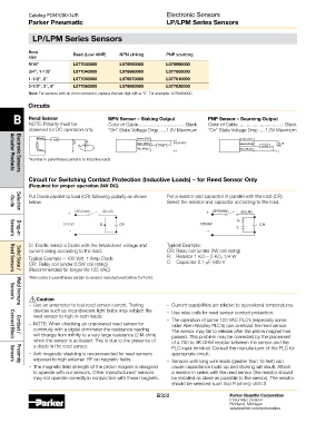
Bore Reed (Low AMP) NPN sinking PNP sourcing
size
9/16" L077030000 L076950000 L076990000
3/4", 1-1/8" L077040000 L076960000 L077000000
1-1/2", 2" L077050000 L076970000 L077010000
2-1/2", 3", 4" L077060000 L076980000 L077020000
Note: For sensors with an 8mm connector, replace the last digit with a ‘C’. For example: L07696000C.
Circuits
B Reed Sensor NPN Sensor – Sinking Output PNP Sensor – Sourcing Output
NOTE: Polarity must be
observed for DC operation only. Color of Cable ...................................Black Color of Cable .................................. Black
“On” State Voltage Drop .....1.5V Maximum
“On” State Voltage Drop .....1.5V Maximum
Brown Load Brown (Red*) (+) Brown (Red*) (+)
Black (White*) 5 to 30 VDC Black (White*) 5 to 30
or LOAD LOAD VDC
AC
DC
Blue Blue (Black*) (–) Blue (Black*) (–)
*Number in parentheses pertains to inductive loads.
Actuator Products
Electronic Sensors
Circuit for Switching Contact Protection (Inductive Loads) – for Reed Sensor Only
(Required for proper operation 24V DC)
Put Diode parallel to load (CR) following polarity as shown Put a resistor and capacitor in parallel with the load (CR).
below. Select the resistor and capacitor according to the load.
Guide
+ (BROWN) (BLUE) + (BROWN) (BLUE)
Selection
R
24VDC D CR 125VAC CR
C
– –
Sensors
Drop-in
D: Diode: select a Diode with the breakdown voltage and Typical Example:
current rating according to the load. CR: Relay coil (under 2W coil rating)
Typical Example – 100 Volt, 1 Amp Diode R: Resistor 1 KΩ − 5 KΩ, 1/4 W
CR: Relay coil (under 0.5W coil rating) C: Capacitor 0.1 µF, 600 V
(Recommended for longer life 125 VAC)
Solid State /
Reed Sensors
*Wire colors in parentheses pertain to sensors manufactured before 10/15/93.
! Caution
Sensors
– Use an ampmeter to test reed sensor current. Testing – Current capabilities are relative to operational temperatures.
Weld Immune
devices such as incandescent light bulbs may subject the – Use relay coils for reed sensor contact protection.
reed sensor to high in-rush loads.
– NOTE: When checking an unpowered reed sensor for – The operation of some 120 VAC PLC’s (especially some
older Allen-Bradley PLC’s) can overload the reed sensor.
continuity with a digital ohmmeter the resistance reading The sensor may fail to release after the piston magnet has
will change from infinity to a very large resistance (2 M ohm) passed. This problem may be corrected by the placement
Cordset /
when the sensor is activated. This is due to the presence of of a 700 to 1K OHM resistor between the sensor and the
Connect Block
a diode in the reed sensor. PLC input terminal. Consult the manufacturer of the PLC for
– Anti-magnetic shielding is recommended for reed sensors appropriate circuit.
exposed to high external RF or magnetic fields. – Sensors with long wire leads (greater than 15 feet) can
Sensors
– The magnetic field strength of the piston magnet is designed cause capacitance build-up and sticking will result. Attach
Proximity
to operate with our sensors. Other manufacturers’ sensors a resistor in series with the reed sensor (the resistor should
may not operate correctly in conjunction with these magnets. be installed as close as possible to the sensor). The resistor
should be selected such that R (ohms) >E/0.3.
B350 Parker Hannifin Corporation
Pneumatic Division
Richland, Michigan
www.parker.com/pneumatics