
Page 389 - Wago_Rail-MountedTerminalBlockSystems_Volume1_2015_US.pdf
P. 389
" 7
387
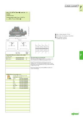
0.08 - 2.5 (4“f-st“)mm²1 AWG 28 - 12
24 VDC
I F 0.025 A max.
Terminal block width 5 mm / 0.197 in
L 6 - 7 mm / 0.26 in 2
<_ 52,5 mm/2.07 in _>
1 Max. insulation diameter: 4.4 mm
2 Strip length, see packaging or instructions.
3 See application notes for:
<_____________ 106 mm/4.17 in _______________> Insulation stop, page 293
Circuit I Circuit II
Pack.
Item No. Unit
Triple-deck LED terminal block with red LED, 7
24 VDC, gray
Circuit I 870-593/281-434 50 Triple-deck diode terminal blocks
Circuit II 870-593/281-413 50 have been specially developed for custom diode circuits,
such as lamp test and collective fault signal circuits.
Using LED terminal blocks, monitoring units can be
designed, e.g., for control and operating circuits. The ter-
minal blocks provide high-density wiring, while maintaining
a width of only 5 mm.
Push-in type jumper bars provide additional options for
custom circuit design.
WMB Multi marking system, plain,
10 strips with 10 markers per card,
stretchable 5 - 5.2 mm
yellow 793-5501/000-002
red 793-5501/000-005
blue 793-5501/000-006
gray 793-5501/000-007
orange 793-5501/000-012
light green 793-5501/000-017
green 793-5501/000-023
violet 793-5501/000-024
5