
Page 20 - Joyce - Options, accessories and controls
P. 20
ACCESSORiES FLEXiBLE COupLiNgS
Joyce Model S and Model F geared Specifying Information Fraction dec. Code Fraction dec. Code
cou plings offer greater torque capacity When specifying hub sizes, please refer 0 .........00 1/2 .........50
than jaw couplings. More gear teeth to the table to determine the three digit 1/16 .........06 9/16 .........56
1/8 .........13
5/8 .........63
around the inner cir cum fer ence of the code. The first digit is the whole number 3/16 .........19 11/16 .........69
coupling, plus high torsional, radial of inches in shaft diameter, while the next 1/4 .........25 3/4 .........75
and angular stiffness mean that you two digits give the decimal equivalents of 5/16 .........31 13/16 .........81
7/8 .........88
3/8 .........38
get a more durable coupling. fractional inches. 7/16 .........44 15/16 .........94
Joyce Mod el S sleeve-type gear 1 63 = 1 5/8" dia. bore
cou plings are avail able in flex/rigid
and flex/flex con fig u ra tions. shaft shaft
diameter diameter
Model F flange-type gear cou plings offer in inches decimal
superior radial-mis align ment ca pa bil i ty and
radial flexibility.
Ordering information — Order must indicate coupling size, coupling type
Model J jaw-type couplings are ideal (S = sleeve; F = flange; J = jaw), large diameter hub code, hub type (F = flex; R = rigid),
for many general industrial applications,
require no lubrication and are resistant to oil, small diameter hub code, hub type (F or R), and fit type (S = slip; I = in ter fer ence).
grease, moisture and other con tam i nants. Example: for sleeve and flange type
10 S 163 F 125 F S
coupling coupling large hub small hub fit
size type diameter type diameter type type
hub code hub code
Example: for jaw type
09 J 100 88
coupling coupling large small Clearance to
size type diameter diameter Align Coupling
hub code hub code
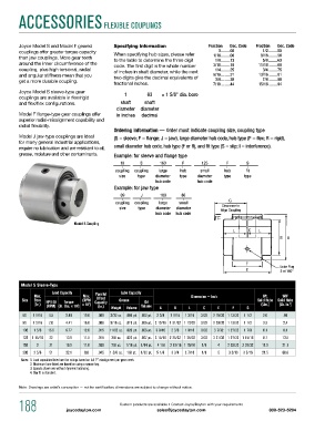
Model S Coupling
Lube Plug
2 at 180°
Model S Sleeve-Type
Load Capacity Lube Capacity
Max. Max. Parallel Dimension — Inch Wt. WR
2
Offset
Size Bore HP/100 Torque (RPM Capacity Grease Oil Solid Hubs Solid Hubs
(In.) (RPM) (In. Lbs. x 10 ) x 10 ) 3 (In.) Weight volume volume A B L C E F G (Lbs.) (Lb. In. ) 2
3
6S 1 1/16 4.5 2.84 19.0 .009 3/32 oz. .006 pt. .002 pt. 2 3/8 1 9/16 1 3/16 3/32 2 15/32 1 13/32 1 1/2 2.0 .86
8S 1 5/16 7.0 4.41 16.0 .009 5/16 oz. .019 pt. .006 pt. 2 13/16 1 31/32 1 13/32 3/32 2 29/32 1 13/32 1 1/2 3.3 2.4
10S 1 5/8 15.5 9.77 12.6 .015 11/32 oz. .020 pt. .006 pt. 3 9/16 2 3/8 1 9/16 3/32 3 7/32 1 27/32 1 7/8 6.1 8.1
12S 1 15/16 22 13.9 11.5 .015 3/8 oz. .022 pt. .007 pt. 3 15/16 2 25/32 1 25/32 3/32 3 21/32 1 27/32 1 15/16 8.7 13.5
15S 2 31 19.5 11.0 .039 7/8 oz. 1/16 pt. 1/64 pt. 4 1/8 2 15/16 1 15/16 1/8 4 2 25/32 2 29/32 11.5 21.1
20S 2 5/8 51 32.1 8.8 .045 1 5/8 oz. 1/8 pt. 1/32 pt. 5 1/8 3 3/4 2 7/16 1/8 5 3 3/16 3 5/16 21.5 60.8
Notes: 1. Load capacities listed are the ratings based on full 1° misalignment per gear mesh.
2. maximum bore listed are based on using a square key.
3. Speeds shown are without dynamic balancing.
4. Slip fit is standard.
Note: Drawings are artist’s conception — not for certification; dimensions are subject to change without notice.
188 joycedayton.com Custom products are available • Contact Joyce/Dayton with your requirements 800-523-5204
sales@joycedayton.com