Page 21 - Joyce - Options, accessories and controls
P. 21

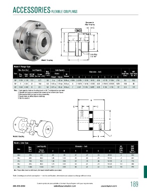
ACCESSORiES FLEXiBLE COupLiNgS


                                                                        Clearance to
                                                                        Align Coupling


                                                                            Lube Plug
                                                                            2 at 180°
                                    Model F Coupling

             Model F Flange-Type
                Max. Bore (In.)  Load Capacity  Lube Capacity
                                       Max.                                Dimension — Inch             Wt.    WR
                                                                                                                 2
             Size  Flex.   Rigid  HP/100   Torque   (RPM    Grease  Oil                               Solid Hubs  Solid Hubs
                 Half  Half  (RPM) (In. Lbs. x 10 ) 3  x 10 ) 3  Weight volume  volume  A  B  L  L´  C  E  F  G  (Lbs.)  (Lb. In. ) 2
             10F  1 5/8  2 1/8  15.5  9.77  6.5  .6 oz.  1/32 pt. 1/64 pt. 4 9/16  2 27/64 1 11/16  1 9/16  3/16  3 7/16  3 7/64  7/16  9.4  18.2
             15F  2  2 3/4  31   19.5   5.3  1 1/8 oz. 1/16 pt. 1/32 pt.  6  2 15/16 1 15/16 1 27/32  5/32  3 15/16 3 29/32  13/32  18.8  66
             20F  2 5/8  3 3/8  51  32.1  5.0  2 1/2 oz. 1/8 pt. 1/16 pt.  7  3 3/4  2 7/16  2 9/32  5/32  4 7/8  4 7/8   1/2  31.4  142
             Notes:  1. Load capacities listed are the ratings based on full 1° misalignment per gear mesh.
                2. Shrouded bolt designs are standard, but exposed will be furnished upon request.
                3. maximum bore listed are based on using a square key.
                4. Speeds shown are without dynamic balancing.
                5. Slip fit is standard.
                                                                             B


                                                              E                   C


                                                                                            A


            Model J Coupling                                                       D         F


             Model J Jaw-Type
                         Max.    Load Capacity                  Dimension — Inch                     Wt.      WR   2
                Size     Bore     Torque                                                             Solid    Solid
                                                                                                              Hubs
                                                                                                     Hubs
                         (In.)   (In. Lbs.)  A        B         C        D         E        F       (Lbs.)   (Lb. In. ) 2
                03J      .375      3.5      .62       .81      .27       .27      .13      #6-32     .1       .003
                05J      .563     26.3      1.08     1.72      .48       .62      .31      1/4-20    .3       .054
                07J      .750     43.2      1.36     2.00      .50       .75      .38      1/4-20    .6       .115
                08J      .875     90.0      1.75     2.12      .50       .81      .31      1/4-20    1.0      .388
                09J      1.000    144.0     2.11     2.12      .50       .81      .44      1/4-20    1.5      .772
             Note: Torque values based on nitrile insert, other insert material available upon request.
            Note: Drawings are artist’s conception — not for certification; dimensions are subject to change without notice.


                                Custom products are available • Contact Joyce/Dayton with your requirements   189
            800-523-5204                      sales@joycedayton.com                  joycedayton.com
   16   17   18   19   20   21   22   23   24   25   26