
Page 23 - Joyce - Options, accessories and controls
P. 23
ACCESSORiES ShAFTiNg
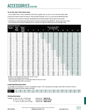
To use this chart, follow these steps:
1. Find a "Shaft Torque" value in the far left column that is greater than, or equal to, your calculated torque value.
2. Move to the second column to find your "Nominal Shaft Diameter" (round up to arrive at an offered shaft size).
3. The third column shows the maximum allowable shaft span before supports (pillow blocks) are required.
4. Compare your actual shaft speed (RPM) with the maximum allowable speed (RPM) for the shaft you have chosen.
If you are above the allowable shaft speed, then increase the shaft size until it falls into the allowable range.
Diameter Selection Chart
Shaft Torque Nominal Maximum** Maximum Allowable RPMs***
(Inch/Lbs.) Shaft Distance Shaft Lengths (Inches)
Diameter* Between
(Inches) Supports 36 48 60 72 84 96 108 120 132 144 156
(Inches)
20 0.51 54.6 1802 1014 649 450 331 253 200 162 134 113 96
40 0.73 61.3 2143 1205 771 536 394 301 238 193 159 134 114
50 0.81 65.5 2372 1334 854 593 436 333 264 213 176 148 126
80 0.87 68.8 2548 1433 917 637 468 358 283 229 190 159 136
100 0.92 71.4 2695 1516 970 674 495 379 299 243 200 168 143
150 1.01 76.3 2982 1677 1074 746 548 419 331 268 222 186 159
200 1.09 80.1 3204 1802 1154 801 589 451 356 288 238 200 171
250 1.15 83.1 3388 1906 1220 847 622 476 376 305 252 212 180
300 1.21 85.7 3546 1995 1277 887 651 499 394 319 264 222 189
350 1.25 87.9 3686 2073 1327 921 677 518 410 332 274 230 196
400 1.30 89.9 3811 2144 1372 953 700 536 423 343 283 238 203
450 1.34 91.7 3925 2208 1413 981 721 552 436 353 292 245 209
500 1.37 93.3 4029 2266 1451 1007 740 567 448 363 300 252 215
600 1.44 96.2 4217 2372 1518 1054 775 593 469 380 314 264 225
700 1.49 98.7 4383 2465 1578 1096 805 616 487 394 326 274 233
800 1.54 100.9 4532 2549 1631 1133 832 637 504 408 337 283 241
900 1.59 102.9 4667 2625 1680 1167 857 656 519 420 347 292 249
1000 1.63 104.7 4792 2695 1725 1198 880 674 532 431 356 299 255
1250 1.72 108.7 5067 2250 1824 1267 931 712 563 456 377 317 270
1500 1.80 112.0 5303 2983 1909 1326 974 746 589 477 394 331 282
1750 1.92 114.9 5511 3100 1984 1378 1012 775 612 496 410 344 293
2000 1.94 117.5 5698 3205 2051 1425 1047 801 633 513 424 356 303
2250 2.00 119.8 5869 3301 2113 1467 1078 825 652 528 437 367 313
2500 2.05 122.0 6025 3389 2169 1506 1107 847 669 542 448 377 321
3000 2.15 125.7 6306 3547 2270 1577 1158 887 701 568 469 394 336
3250 2.19 127.4 6434 3619 2316 1608 1182 905 715 579 479 402 343
3500 2.23 129.0 6554 3687 2359 1639 1204 922 728 590 487 410 349
4000 2.31 131.9 6776 3812 2440 1694 1245 953 753 610 504 424 361
4500 2.38 134.5 6979 3926 2512 1745 1282 981 775 628 519 436 372
5000 2.44 136.9 7165 4030 2579 1791 1315 1008 796 645 533 448 382
6000 2.55 141.1 7499 4218 2700 1875 1377 1055 833 675 558 469 399
7000 2.65 144.8 7794 4384 2806 1949 1432 1096 866 701 580 487 415
Note: Shaded area exceeds maximum distance between supports. pillow blocks are required.
*Shaft diameter is based on 0.08 degrees twist per foot of length.
**maximum distance between supports is based on a maximum allowable deflection of 0.01 inches per foot of length.
***maximum allowable Rpms is based on 80% of critical shaft speed.
Length Specifying Information
Joyce shafts can be ordered in 1/16 inch increments of length. When specifying shaft length, please refer to the table below to
determine the decimal code for fractions of length.
Fraction 0 1/16 1/8 3/16 1/4 5/16 3/8 7/16 1/2 9/16 5/8 11/16 3/4 13/16 7/8 15/16
Decimal .00 .06 .13 .19 .25 .31 .38 .44 .5 .56 .63 .69 .75 .81 .88 .94
Ordering Information
Example: A. For a 1/2" dia. x 33 3/8" long Part Number = S50-33.38
B. For a 1 1/4" dia. x 110" long Part Number = S125-110.00
C. For a 2 1/4" dia. x 58 7/16" long Part Number = S225-58.44
Custom products are available • Contact Joyce/Dayton with your requirements 191
800-523-5204 sales@joycedayton.com joycedayton.com