
Page 3 - Destaco - RDM Series Rotary Index Drives
P. 3
rdm Series Rotary Index Drives
Precision Indexing | How To Order
Control Description
1 1 hp 120V 80RDM,601RDM & 902RDM only
2 1 hp 240V 80RDM,601RDM & 902RDM only
3 1 hp 440V 80RDM,601RDM & 902RDM only
Base Model Description 4 2 hp 240V 1100RDM & 1305RDM only
80RDM w/ R180 reducer & 1/3 hp AC motor (220/440V) 5 2 hp 440V 1100RDM & 1305RDM only
601RDM w/ R180 reducer & 1/3 hp AC motor (220/440V) 6 3 hp 240V 1800RDM only
902RDM w/ R225 reducer & 1 hp AC motor (220/440V) 7 3 hp 440V 1800RDM only
1100RDM w/ KH47 reducer & 1-1/2 hp AC motor (220/440V)
1305RDM w/ 7300C reducer & 2 hp AC motor (220/440V) Clutch Description
1800RDM w/ 7400C reducer & 3 hp AC motor (220/440V) 1 Standard detector plate
2 Detector plate with hole
Setting (in-lbs)
A 420
B 620
C 750
D 1150
E 1750
F 2950
G 4000
* Eg: For 601RDM
Motion Stops Index Period Index Reducer Ratio Reducer
Mounting
A 2 330 (See Figure 3) 1100RDM Mounting Signal Switch Signal Switch Side
B 3 330 A 15 15.86 (See Figure 4) (See Figure 2)
C 4 330 1 B 20 19.58 M Mechanical R Reducer
D 6 330 2 C 25 24.06 A J D Double S Shaft
E 8 330 3 D 30 29.37 B K P Proximity
F 12 330 4 E 40 39.61 C L Example: MR, MS, DR, DS, PR or PS
G 16 330 5 F 50 48.95 D M Note about signal switch options:
6 G 60 56.83 E N a) Mechanical is a single switch with cam.
H 15 -- F P b) Proximity option is a mounting
G R bracket for 8 or 12 mm proximity switch.
H S A proximity switch will not be supplied.
Cam supplied as target.
Other Motions (stops and index periods) available. Contact your DE-STA-CO sales representative for more information.
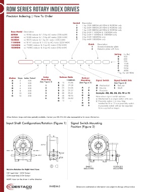
Input Shaft Configuration/Rotation (Figure 1) Signal Switch Mounting
Position (Figure 2)
CW CCW
SHAFT REDUCER
Relative Rotation for Right Hand Cam: MOUNTED MOUNTED
CW Input Side 1 CCW Output
CCW Input Side 2 CW Output
NOTE: Input can be driven in either direction
IN-RDM-3 Dimensions and technical information are subject to change without notice