
Page 80 - Linde - VT1 Modular, modular system for LSC manifold valve plates
P. 80
6 | Configuration of the valve system.
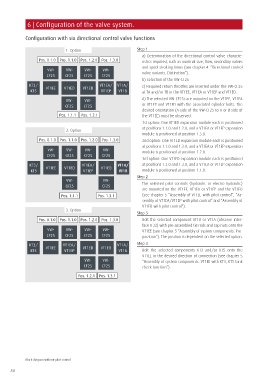
Configuration with six directional control valve functions
1. Option Step 1
a) Determination of the directional control valve characte-
Pos. 0.1.0 Pos. 1.1.0 Pos. 1.2.0 Pos. 1.3.0 ristics required, such as nominal size, flow, secondary valves
and spool stroking times (see chapter 4 “Directional control
VW- VW- VW- VW-
CF25 CF25 CF25 CF25 valve variants. Distinction”).
b) Selection of the VW-CF25
KT3/ VT1EE VT1ED VT1ED VT1EA/ VT1A/ c) Required return throttles are inserted under the VW-CF25
KT5 VT1EP VT1B at TA and/or TB in the VT1EE, VT1EA or VT1EP and VT1ED.
VW- VW- d) The selected VW-CF25s are mounted on the VT1EE, VT1EA
CF25 CF25 or VT1EP and VT1ED with the associated cylinder bolts. The
desired orientation (A side of the VW-CF25 to A or B side of
Pos. 1.1.1 Pos. 1.2.1 the VT1EE) must be observed.
1st option: One VT1ED expansion module each is positioned
at positions 1.1.0 and 1.2.0, and a VT1EA or VT1EP expansion
2. Option
module is positioned at position 1.3.0.
Pos. 0.1.0 Pos. 1.1.0 Pos. 1.2.0 Pos. 1.3.0 2nd option: One VT1ED expansion module each is positioned
at positions 1.1.0 and 1.3.0, and a VT1EA or VT1EP expansion
VW- VW- VW- VW- module is positioned at position 1.2.0.
CF25 CF25 CF25 CF25
3rd option: One VT1ED expansion module each is positioned
KT3/ VT1EE VT1ED VT1EA/ VT1ED VT1A/ at positions 1.2.0 and 1.3.0, and a VT1EA or VT1EP expansion
KT5 VT1EP VT1B module is positioned at position 1.1.0.
Step 2
VW- VW-
CF25 CF25 The selected pilot controls (hydraulic or electro-hydraulic)
are mounted on the VT1EE, VT1EA or VT1EP and the VT1ED
Pos. 1.1.1 Pos. 1.3.1 (see chapter 5 “Assembly of VT1EE with pilot control”, “As-
sembly of VT1EA/VT1EP with pilot control“ and “Assembly of
VT1ED with pilot control”).
3. Option
Step 3
Pos. 0.1.0 Pos. 1.1.0 Pos. 1.2.0 Pos. 1.3.0 Bolt the selected component VT1B or VT1A (observe inter-
face IF32) with pre-assembled tie rods and cap nuts onto the
VW- VW- VW- VW- VT1EE (see chapter 5 “Assembly of system components. Pre-
CF25 CF25 CF25 CF25 paration”). The position is dependent on the selected option.
KT3/ VT1EE VT1EA/ VT1ED VT1ED VT1A/ Step 4
KT5 VT1EP VT1B Bolt the selected components KT3 and/or KT5 onto the
VT1EE in the desired direction of connection (see chapter 5
VW- VW- “Assembly of system components. VT1EE with KT3, KT5 tank
CF25 CF25 check function”).
Pos. 1.2.1 Pos. 1.3.1
Block diagram without pilot control
80