
Page 82 - Linde - VT1 Modular, modular system for LSC manifold valve plates
P. 82
6 | Configuration of the valve system. Example configuration 1
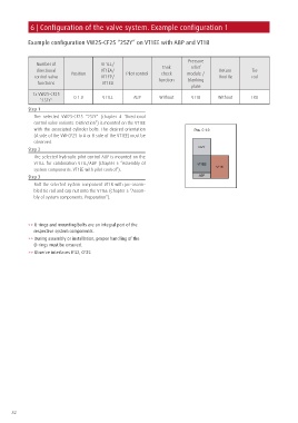
Example configuration VW25-CF25 “25ZY” on VT1EE with ABP and VT1B
Pressure
Number of VT1EE/ Tank relief
directional VT1EA/ Return Tie
check
control valve Position VT1EP/ Pilot control function module / throttle rod
blanking
functions VT1ED
plate
1x VW25-CF25
``25ZY`` 0.1.0 VT1EE ABP Without VT1B Without TR0
Step 1
The selected VW25-CF25 “25ZY” (chapter 4 ‘Directional
control valve variants. Distinction”) is mounted on the VT1EE
with the associated cylinder bolts. The desired orientation
(A side of the VW-CF25 to A or B side of the VT1EE) must be
observed.
Step 2
The selected hydraulic pilot control ABP is mounted on the
VT1EE for combination VT1E/ABP (Chapter 5 “Assembly of
system components. VT1EE with pilot control”).
Step 3
Bolt the selected system component VT1B with pre-assem-
bled tie rod and cap nut onto the VT1EE (Chapter 5 “Assem-
bly of system components. Preparation”).
>> O-rings and mounting bolts are an integral part of the
respective system components.
>> During assembly or installation, proper handling of the
O-rings must be ensured.
>> Observe interfaces IF32, CF25
82