
Page 86 - Linde - VT1 Modular, modular system for LSC manifold valve plates
P. 86
6 | Configuration of the valve system. Mounting the control plate
The pre-configured control plate must be mounted at the installation location. For this purpose, system components VT1EE, VT1B and
VT1A are equipped with appropriate M12 threaded holes. In order to ensure a firm hold, screws with strength 8.8 and appropriate
tightening torques must be used.
Important note:
In any case, an additional stress-free bearing must be guaranteed!
For this purpose, the following conditions apply:
>> If the VT1EE base plate is used only without an IF32 expansion module, no further measures need to be taken. The control
plate is mounted only at the existing threaded holes M12/16 deep of the VT1EE base plate.
>> If IF32 expansion modules are used, the customer must provide an additional stress-free mounting to support the mass
and acceleration forces that occur. The corresponding ¬threaded holes are available on the VT1B blanking plate and on the
VT1A pressure relief module.
In addition, the respective installation location and use must be analyzed in detail by the user.
The position of the mountings can be derived from the dimensional drawings of the system components.
Information for special applications is available on request.
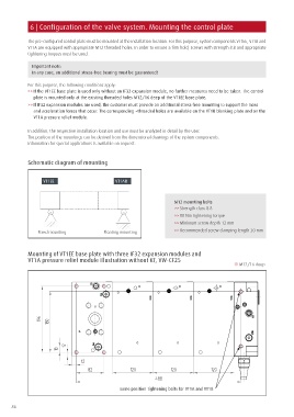
Schematic diagram of mounting
VT1EE VT1AB
M12 mounting bolts
>> Strength class 8.8
>> 80 Nm tightening torque
>> Minimum screw depth 12 mm
Fixed mounting Floating mounting >> Recommended screw clamping length 30 mm
Mounting of VT1EE base plate with three IF32 expansion modules and
VT1A pressure relief module Illustration without KT, VW-CF25
M12/16 deep
same position tightening bolts for VT1A and VT1B
86