
Page 122 - Destaco - Clamping Technology
P. 122
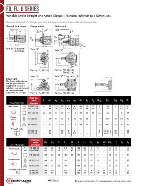
FO, FL, G Series


      Variable Stroke Straight Line Action Clamps | Technical Information | Dimensions


      One-hand operation (the plunger and the hand wheel are operated simultaneously)
      Through hole mount   Flange mount         Foot mount
                                                * without counter-force
                                                effect
                                                   rapid
                                                   stroke S
                                                   clamping
                                                   stroke*


      Part no.   G-082/40   View “X”
             G-122/45                           View “Y”


                           Part no. FL-122/45   Part no.    FO-082/40
                                                         FO-122/45
                           View “X”             View “Y”
      Important
      The Straight Line clamps
      are designed only for
      axial load. In case of
      side load, we recommend
      an additional radial
      support of the plunger.  Part no. FL-162/60  Part no.  FO-162/60

                          Part no.
                            with      A   A 1   A 2  A 3  A 4  A 5   B    B 1  B 2  D h8   D 1    D 2  D 3   D 4
         Mounting type    plunger          ~    ~    ~                    ~
        Foot mount       FO-082-40    –   37   15,3  10    5    6    44   56   35    8     30      –   4,5   16
                         FO-122-45    –   44    19   12   6,3  8,5   52   68   40    12    35          6,5   20

                         FO-162-60   40   62    11   12   12    10   70   90   52    16    46      –    9    25
          Flange
          mount          FL-122-45    –   44    44   12    6    85   52   68    –    12    30f7   40   6,5   20

                         FL-162-60    –   60    –    14   14    10   68   73    –    16    40f7   52    9    25
          Through hole
             mount       G-082-40     –   37    –    10    8    6    –     –    –    8   M24x1,5  35    –    16
                         G-122-45     –   44    –    12   10   8,5   –     –    –    12  M30x1,5  40    –    20


                            Part no.
                             with      D 5  D 6    E    E 1   H    L    L 1   S 2  S 3  SW   SW 1  T    T 1  T 3
          Mounting type     plunger                           ~    ~                     ~
         Foot mount       FO-082-40    M5   40    18    9,2  36   128   26    9    2,5   –    8    8    –    8
                          FO-122-45    M6   75    20   12,5  42   153   27    15   2,5   –    11   12   –    10

                          FO-162-60    M8   75    30   14.8  58   196   35    18    3    –    13   15   1    14
        Flange mount
                          FL-122-45    M6   52     –   12,5   –   153   27    15   2,5   –    11   12   –    10

                          FL-162-60    M8   75    28   14,8   –   196   35    18    3    –    13   15   1    14
        Through hole mount
                          G-082-40     M5   40     –    9,2   –   128   26    9    2,5   30   8    12   –    8
                          G-122-45     M6   52     –   12,5       153   27    15   2,5   35   11   12   –    10

                                          MC-VSC-5               Dimensions and technical information are subject to change without notice