
Page 123 - Destaco - Clamping Technology
P. 123
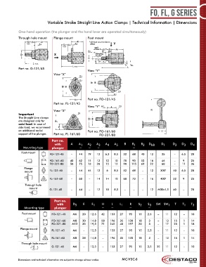
FO, FL, G Series


                             Variable Stroke Straight Line Action Clamps | Technical Information | Dimensions


            One-hand operation (the plunger and the hand lever are operated simultaneously)
            Through hole mount   Flange mount        Foot mount
                                                      * without counter-force
                                                       effect
                                                         rapid
                                                         stroke S
                                                          clamping
                                                          stroke*


            Part no. G-121/45
                                                     View “Y”
                                 View “X”


                                                     Part no. FO-121/45
                                 Part no. FL-121/45
                                                     View “Y”
                                 View “X”
            Important
            The Straight Line clamps
            are designed only for
            axial load. In case of
            side load, we recommend
            an additional radial                     Part no.   FO-161/60
            support of the plunger.  Part no. FL-161/60     FO-221/80

                                Part no.
                                 with      A    A 1  A 2  A 3   A 4  A 5   B    B 1  B 2  D h8   D 1    D 2  D 3  D 4
               Mounting type    plunger         ~    ~     ~                    ~
              Foot mount
                               FO-121-45   –    44   19    12   6,3  8,5  52    68   40   12     35      –   6,5  20
                               FO-161-60   40   62   11    12   12   10   70    90   52   16     46      –    9   25
                               FO-221-80   50   75   13    20   15   12   90   115   69   22     60      –   11   36
               Flange
                mount          FL-121-45   –    44   44    12   6    8,5  52    68    –   12    30f7    40   6,5  20

                               FL-161-60   –    60    –    14   14   10   68    73    –   16    40f7    52    9   25
                Through hole
                  mount        G-121-45    –    44    –    12   10   8,5   –    –     –   12   M30x1,5  40    –   20


                                 Part no.
                                   with     D 5   E    E 1    H    L    L 1   R    S 2   S 3  SW  SW 1   T   T 1   T 3
               Mounting type     plunger                     ~     ~          ~          ~
              Foot mount        FO-121-45   M6    20   12,5  42   153   27    95   15    2,5   –   11   12    –    10

                                FO-161-60   M8    30   14,8  58   196   35   130   18    3     –   13   15    1    14
                                FO-221-80   M12   35   19,5  71   245   40   197   20    3     –   17   25    1    18
             Flange mount
                                FL-121-45   M6     –   12,5   –   153   27    95   15    2,5   –   11   12    –    10

                                FL-161-60   M8    28   14,8   –   196   35   130   18    3     –   13   15    1    14
              Through hole mount
                                G-121-45    M6     –   12,5   –   153   27    95   15    2,5  35   11   12    –    10


            Dimensions and technical information are subject to change without notice  MC-VSC-6