
Page 119 - Destaco - Clamping Technology
P. 119
FO, FL, G Series
Variable Stroke Straight Line Action Clamps | Operation
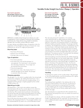
Two-hand operation One-hand operation
(the plunger and the hand (the plunger and handle
lever are operated separately) lever/hand wheel are
operated simultaneously)
rapid stroke
clamping
stroke
DESTACO‘s variable stroke Straight Line clamps are used The clamping strokes S1 specified in this catalog
in applications where workpiece thicknesses and workpiece were measured with no opposing forces present while
tolerances vary. These clamps are suitable for clamping measurements were taken. When clamping this product
between ribs and hollow spaces difficult to reach. against a workpiece, the clamping stroke S1 is reduced by
Compact design and different types of operation allow for the force-locking connection between the plunger and the
application of the Straight Line clamps in fixtures for mass workpiece. The straight-action clamp is unlocked by turning
production as well as for single part production. the hand lever or the hand wheel counter-clockwise. This
method is used for both the one-hand and the two-hand
Mounting types operation types. This counter-clockwise rotation makes the
• Foot base (FO Series) conical sleeve (4) and the threaded sleeve (8) or (9) move
• Flange mount (FL Series) backward. The pressure spring (7) pushes back the relieved
• Through hole mount (G Series) ball bearings (5) via the pressure ring (6).
The force-locking connection between the slotted clamping
Type of operation
sleeve and the plunger can be moved freely again. Straight
• Two hand operation Line clamps which are two-hand operated can also be
• The hand lever (10) and the plunger (1) applied to pull actions when the plunger is inserted in the
are separate. The hand lever is connected to clamp´s housing in the opposite direction. On the one
the clamping mechanism. The plunger can hand operated clamp, the rotation inducing the clamping
be removed from the clamp stroke S1 is directly transmitted from the plunger (2) or the
• One-hand operation hand wheel to the threaded sleeve (9) via a groovespring
connection. The clamping and unclamping operations are
• The hand lever (10) or the hand wheel (11) executed in the same way as described before.
and the plunger (2) are linked. The plunger
is retained within the clamp. Handling
Clamping operation To change the position of the handle while in the clamped
or the unclamped position, pull the hand lever off its spline
The plunger (1) or (2) which is guided within the clamp body (12) and set it in the desired position.
contacts the workpiece. By rotating the hand lever (10) or
the hand wheel (11) clock-wise the clamping stroke, S1 is Important
engaged and the plunger is tightly gripped by the slotted The holding forces specified in the catalog refer to the
clamping sleeve (3). maximum load exerted on the clamp by counter-forces.
Operating principle For details concerning the clamping force FS exerted
on the workpiece by the clamp and depending on the
The hand lever´s (10) clock-wise rotation causes the
threaded sleeve (8) and the conical sleeve (4) to which it is operation force FB (manual force), please see the chart
connected to move in the direction of the arrow shown in on the next page.
the drawing. The conical sleeve produces a force-locking The clamping force is proportional to the operation force.
connection between the slotted clamping sleeve (3) and the The achieved clamping force must not exceed the maximum
plunger by means of the ball bearings (5) located at the holding force.
clamping sleeve´s perimeter. As the Straight Line clamps, with the exception of the F-160
Due to the force-locking connection, the plunger rotates and model, are designed only for axial load, we recommend to
produces the clamping stroke S1. The plungers rotation may use an additional radial support for the plunger in the event
be compensated for by means of a swivel hold-down piece. of side load.
Dimensions and technical information are subject to change without notice MC-VSC-2