
Page 246 - Destaco - Clamping Technology
P. 246
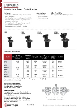
8700 series


      Pneumatic Swing Clamps | Product Overview


      Features:                                        Applications:         Also Available:
      •  Alternative solution to swing clamps when     •  Assembly &         See page MC-PSC-39 for jam nuts
        space is limited                                 welding fixtures
      •  The clamping lever  may be positioned left,   • Light machining
        forward, or right (relative to ports) within
        the same clamp body
      •  Threaded body with upper flange mount
      •  Non-toggle locking linkage
      •  Clamping arm and spindle included


      8725                     8732                     8740                     8750
                               8732G                    8740G                    8750G


      Technical Information


                        Vertical     Clamping                    Air
         Model     Clamping Stroke*    Force     Bore Size   Consumption     Weight   Seal Kit
                                                                        ‡
                                            †
                                                                             [lb.]kg
                                                  [in.]mm
                        [in.]mm        [lbf.]N                 [in. ]cm 3
                                                                  3
                         [0.10]         [43]       [0.98]       [0.004]       [1.3]
       8725                                                                            872500
                          2,5           195         25           0,11         0,6
       8732                             [64]       [1.26]       [0.008]       [2.2]    873200
       8732G             [0.12]         285         32           0,23         1,0
       8740               3,2           [106]      [1.57]       [0.014]       [2.6]    874000
       8740G                            470         40           0,41         1,2
       8750              [0.15]         [167]      [1.97]       [0.023]       [4,4]    875000
       8750G              3,8           745         50           0,64         2,0

                                                         †
      * Equal to approx. 6° above horizontal with standard clamping arm.    at 5bar [72psi].
      ‡ per double stroke at 5bar [72psi].
      Operating Pressure Range:
      3bar [45psig] to 7bar [100psig]
      Max. Operating Temperature:
      -10°C to 80°C [14°F to 175°F]
      Application Note:
        If using clamping arms other than standard, the
      length must not exceed 1.5X the overall length of
      the standard arm.
                                                                       Left      Forward     Right
      The inlet air flow rate should be adjusted to
      position the arm in no less than 1/2 second for                 Levers can be positioned in one of three
                                                                       positions in relation to the air ports.
      standard arms and no less than 1 second in the
      case of an extended arm.
                                         MC-PSC-37               Dimensions and technical information are subject to change without notice