
Page 252 - Destaco - Clamping Technology
P. 252
pneumatic power cylinders
Features
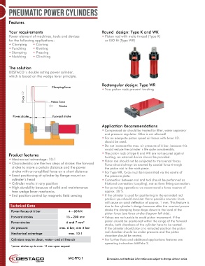
Your requirements Round design: Type K and WK
Power element of machines, tools and devices • Piston rod with male thread (Type K)
for the following applications: or ISO fit (Type WK)
• Clamping • Coining
• Punching • Riveting
• Stamping • Pressing
• Notching • Clinching
The solution
DESTACO´s double acting power cylinder,
which is based on the wedge lever principle.
Rectangular design: Type WR
Clamping force
• Two piston rods prevent twisting
Force Piston force
Stroke
Power stroke Forward stroke
Application Recommendations
• Compressed air should be treated by filter, water separator
and pressure regulator. Oiler is not allowed!
• For an adequate piston speed air hoses with 6mm I.D.
should be used.
• Do not increase the max. air pressure of 6 bar, because this
would reduce the cylinder´s life cycle considerably.
Product features • The piston rods of type K and WK are not secured against
twisting, an external device should be provided.
• Mechanical advantage: 10:1 • Piston rod should not be subjected to transversal forces.
• Characteristic are the two steps of stroke: the forward Force should always be exerted by coaxial force through
stroke to move a certain distance and the power the piston rod to the work piece.
stroke with an amplified force on a short distance • For Type WR, force must be transmitted via the centre of
• Exact positioning of cylinder by flange mount on the pressure plate.
cylinder’s head • Connection between rod and tool should be performed as
• Cylinder works in any position frictional connection (coupling), not as form fitting connection.
• High durability because of solid and maintenance • For punching operations we recommend a force reserve of
free wedge lever mechanics. approx. 30 %.
• End position control by magnetic field sensing • If the cylinder is used for positioning in the extended rod
position you should consider that a possible counter-force
will cause an axial deflection of approx. 1 mm. This feature is
Technical Data due to the cylinder’s design because after the nominal power
stroke the clamping force drops down to the level of the
Power forces at 6 bar 4 – 60 kN
piston force (see force-stroke diagram left side).
Forward strokes 15 – 200 mm • Valves are not usable to avoid piston movement. If the
Power strokes 6 and 7 mm* piston should be positioned within the range of the forward
stroke, both chambers of the cylinder have to be vented.
Air pressure max. 6 bar, min 3 bar If the cylinder should stay at a retracted position the piston
Mechanical advantage max. 10:1 rod chamber should be under pressure and the piston
chamber should be vented.
Cylinders require clean, water- and oil free air • For further facts and additional applications features see
operating instruction MAPnkz-2.
*power strokes up to max. 12 mm upon request
MC-PPC-1 Dimensions and technical information are subject to change without notice