Page 58 - Destaco - Clamping Technology
P. 58

2017 Series


      Horizontal Hold Down Clamps | Product Overview


      Features:                                        Applications:         Also Available:
      • Increased handle clearance reduces pinch points  • Checking fixtures  See page MC-ACC-1 for accessories
      • Common mounting hole pattern to Model 217      • Assembly & test     Accommodates M6 or ¼”
      • Fixed handle pivot provides smooth action      • Light machining     spindle accessory
      • Over 2½ times the holding capacity Model 217   • Woodworking
      • BLK models feature a black, non-reflective finish  • Closures


        Covered under one or more U.S./International Patents
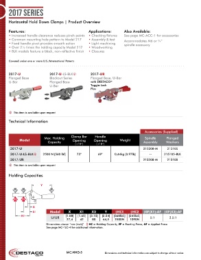


      2017-U                   2017-U-LS-BLK           2017-UR
      Flanged Base             Blackout Series          Flanged Base, U-Bar
      U-Bar                    Flanged Base             with DESTACO ®
                               U-Bar                    Toggle Lock
                                                        Plus


       This item is available upon request

      Technical Information


                                                                                         Accessories (Supplied)
                                            Clamp Bar      Handle
                            Max. Holding                                                 Spindle      Flanged
             Model                           Opening      Opening         Weight
                              Capacity                                                  Assembly      Washers
                                               (+10°)       (+10°)
       2017-U                                                                           215208-M       215105
       2017-U-LS-BLK      2500 N [560 lbf]     73°          69°       0,44kg [0.97lb]      --       215105-BLK
       2017-UR                                                                          215208-M       215105
       This item is available upon request


      Holding Capacities


                          Y
          EF   EF               AF

         HC   HC
          2    1
                     X
                     X1        Model       X     X1      X2      Y     ‡HC1     ‡HC2     ‡EF(X1):AF ‡EF(X2):AF
              X2                         [1.08]  [1.65]   [3.15]  [2.54]  [560lbf.]  [245lbf.]
                                U/UR                                                        5:1         2.5:1
                                          27,4    42     80     64,5   2500N    1090N
                             Dimensions shown “mm [inch]”   ‡ HC = Holding Capacity, EF = Exerting Force, AF = Applied Force
                             See page MC-TEC-4 for additional information.


                                         MC-HHD-5                Dimensions and technical information are subject to change without notice
   53   54   55   56   57   58   59   60   61   62   63