
Page 10 - Exlar - Hazardous location GSX/GSM class 1 division 2
P. 10
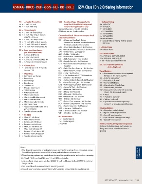
GSMAA - BBCC - DEF - GGG - HIJ - KK - (XX..) GSM Class I Div 2 Ordering Information


                 AA =   Actuator Frame Size        GGG =  Feedback Type (Also specify the   I = Voltage Rating
                 30  =  3 inch (75 mm)                  Amplifier/Drive Model being used   A = 24 Volt DC
                 40  =  4 inch (100 mm)                 when ordering) Resolver Only  B = 48 Volt DC
                                                   Standard Resolver – Size 15, 1024 line   C = 120 Volt DC
                 BB  =  Stroke Length              (2048 cts) per rev, 2 pole resolver   1 = 115 Volt RMS
                 03  =  3 inch (76 mm) GSM30                                          3 = 230 Volt RMS
                 06  =   6 inch (152 mm) all models   Custom Feedback: Please contact your local   5 = 400 Volt RMS
                      GSM30 = 5.9 inch             sales representative:
                 08  =  8 inch (203 mm) GSM40      XX1  =  Wiring and feedback device   6 = 460 Volt RMS
                                                                                      X =  Special Voltage Rating - Not to exceed
                 10  =  10 inch (254 mm) all models    information must be provided and new   460 Vrms
                 12  =   12 inch (305 mm) all models   feedback callout will be created
                 18  =  18 inch (457 mm) GSM30, 40  AB6  =  Allen BradleyRockwell - Std Resolver  J = Motor Poles
                 CC  =   Lead (position change     AM3 =  Advanced Motion Control - Std Resolver  8 = 8 Motor Poles
                      per motor revolution)        AP1  = API Controls - Std Resolver  KK = Motor Speed
                 01  =   0.1 inch (2.54 mm)        BD2  =  Baldor - Std Resolver      24 = 2400 rpm, GSX/M50, GSX60
                 02  =   0.2 inch (5.08 mm)        BM2 = Baumueller - Std Resolver    30 = 3000 rpm, GSX/M30, 40
                 05  =   0.5 inch (12.7 mm) GSM30, 40  BR1  = B&R Automation - Std Resolver  01-99 = Rated speed in RPM x 100
                                    3
                 08  =  0.75 inch (19.05 mm) GSM40  CO2  = Copely Controls - Std Resolver
                                                   CT5  =  Control Techniques/Emerson - Std
                 D  =  Connections                     Resolver                       XX .. XX =  Options (please list
                 T  =   Terminal Box with NPT ports   DT2  =  Delta Tau Data Systems - Std Resolver  desired options)
                      (see pg 135)                 EL1  =  Elmo Motion Control - Std Resolver  Travel Options
                 E  =  Mounting                    EX4  =  Exlar - Std Resolver       NI   =  Non-incendive construction required
                 B  =  Front and rear flange       EX5  =  Std Resolver with KTY84 thermistor  for Class 1, Div 2 (see pg 145)
                 C  =  Rear clevis                 IF1  = Infranor - Std Resolver     AR  = External anti-rotate 4
                 F  =  Front flange                IN6  =  Indramat/Bosch-Rexroth-Std Resolver  PF  = Preloaded follower 1
                 R  =  Rear flange                 JT1  =  Jetter Technologies - Std Resolver  RB  = Rear electric brake
                 S  =  Side mount                  KM5 =  Kollmorgen/Danaher - Std Resolver  RD  = Manual drive, Simple Rear
                 D  =  Double side mount           LZ5  =  Lenze/AC Tech - Std Resolver  SD  = Manual drive, Side Hex
                 T  =  Side trunnion               MD1 = Modicon - Std Resolver       HW =  Manual drive, handwheel including
                 E  =  Extended tie rods           MG1 = Moog - Std Resolver              Class I, Div 2 interlock switch
                 J   =  Metric side mount          MX1 = Metronix - Std Resolver      P5  =  IP65S
                 K  =  Metric double side mount    MN4 =  Momentum - Std resolver     PB  =  Protective bellows 5
                 Q  =  Metric side trunnion        OR1  = Ormec - Std Resolver        SR  =  Splined main rod 6
                 M  =  Metric extended tie rods    PC7  =  Parker Compumotor - Std Resolver  XT  =  Special travel options, high temp
                                                                                               5
                 G  =  Metic rear clevis           PC0  =  Parker Compumotor - Std Resolver  bellows ,  or angular contact bearings
                 Z  =   Clevis mount with same pin to   PS3  =  Pacific Scientific - Std Resolver
                      pin as SR Series             SM2 =   Siemens - Std Resolver     Housing Options     2
                 X  =  Special (please specify)    SW1 =   SEW/Eurodrive - Std Resolver   EN  = Electroless nickel plating
                                                   WD1 = Whedco - Std Resolver        HC  = type III anodizing hard coat 2
                 F  =  Rod End                                                        XH  = Special housing option
                 M  =  Male, US std thread         H = Motor Stacks                   XL  = Special lubrication (greases only)
                 A  =  Male, metric thread         1 = 1 stack magnets                XM = Special motor option
                 F  =  Female, US std thread       2 = 2 stack magnets
                 B  =  Female, metric thread       x = Special                        ##### = Part No. Designator for Specials
                 W  =   Male, US std thread SS 6                                      Optional 5 digit assigned part number to
                 R  =   Male metric thread SS 6                                       designate unique model numbers for
                 V  =   Female, US std thread SS 6                                    specials.
                 L  =  Female metric thread SS 6
                 X  =  Special (please specify)


                   Notes:
                   1.  The dynamic load rating of preloaded screws is 63% of the rating of non-preloaded screws.
                    Travel life of preloaded screw is 25% of non-preloaded screw of same size.                        CID2, GSX &   GSM Series
                   2.  These housing options may also indicate the need for special material main rods or mounting.
                   3.  0.75 inch (19.05 mm) lead N/A over 12 inch (450 mm) stroke.
                   4.  A second anti-rotate arm is used on GSM30 10 inch and longer stroke; GSM40 12 inch and
                    longer stroke.
                   5.  Not available with extended tie rod mounting option.
                   6. Consult your local sales representative when ordering splined stainless steel main rod.


                                                                                           952.500.6200 | www.exlar.com    153ww.exlar.com    153
                                                                                           952.500.6200 | w