Page 8 - Exlar - Hazardous location GSX/GSM class 1 division 2
P. 8

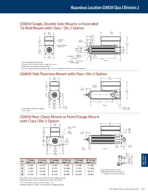
Hazardous Location GSM30 Class I Division 2


                 GSM30 Single, Double Side Mounts or Extended
                 Tie Rod Mount with Class I Div 2 Option

                                        3.45                                               6.97
                                         88                                                177
                                                                            1.32
                                                                            33.5
                                                                            .962
                                3.19             3.536  B.C.     1/4-20     24.4
                                 81              89.8            UNC-2A     .090
                                                                            2.3                         6.3
                                                Single Side Mount                                       159
                                                On This side
                                                                  +.000
                                                               2.000 -.003                          1.750
                                                                  0
                                3.046                          50.8 -0.08                            44.5
                                77.4
                                                              +.0000[.00]    .250
                                        3.046             .2500[6.35]  - .0005[.01]  6.4
                                        77.4                .375[9.53]             Dim "B"
                                                        1/4-20 UNC       .375[9.53]   Dim "A"
                  1. Three mounting styles shown          (4x SSM, 8X DSM)
                  2.  Shown view is standard side for single side mount
                  * If “M” metric tie rod option, thread = M6 x 1
                  *  If “J” or “K” metric side mount options, M6 x 1.0   9 mm with Ø 6 mm M7  9 mm Dowel Hole
                 GSM30 Side Trunnion Mount with Class I Div 2 Option
                                            3.45                                          6.97
                                             88                                           177
                                      3.19                                    1.500
                                      81                                     38.1
                                                                   1.32
                                                                   33.5                                 6.3
                                                                                                        159

                                            3.046
                                            77.4                                 Dim "C"
                                            3.546
                                            90.1                                     Dim "A"
                                            3.921    1.000
                                                                                                      1.000 ±.001
                  *  If “Q” metric side trunnion option,   99.6  25.4                                 25.4 ±0.03
                   Ø 25 mm h7
                 GSM30 Rear Clevis Mount or Front Flange Mount
                 with Class I Div 2 Option
                                                                                          6.97
                                             3.45                                         177
                                             88
                                                         .250 ±.0005
                                                         6.35                                            +.002
                                                                                                       .750 -.001
                                    3.19                 .397      1.32                                  +.05
                                    81                   10.08     33.5                               19.05  -.03
                                   3.046              2.430
                                    77.4              61.72
                                                                                               .993       R .750
                                             3.688                                             25.2       19.1
                                             93.7                   .438             Dim "D"
                                             5.250                  11.13
                                             133.4
                                             5.940                                                     2.500
                                             150.9                                                      63.5
                       3" (76 mm)   6" (152 mm)   10" (254 mm)   12" (305 mm)   14" (355 mm)   18" (457 mm)   1.250   CID2, GSX &   GSM Series
                  Dim                                                                                     31.8
                      Stroke in (mm)  Stroke in (mm)  Stroke in (mm)  Stroke in (mm)  Stroke in (mm)  Stroke in (mm)
                   A    8.2 (209)  10.7 (272)  15.2 (387)  17.2 (437)  19.2 (488)  23.2 (590)
                   B    6.1 (156)  8.6 (219)  13.1 (333)  15.1 (384)  17.1 (435)  21.1 (536)
                                                                                   1. Two mounting styles shown
                   C    5.4 (137)  8.0 (203)  10.0 (254)  12.0 (305)  14.0 (356)  18.0 (457)  2.  With flange mount, dimension A
                   D    9.5 (241)  12.0 (304)  16.5 (418)  18.5 (469)  20.5 (520)  24.5 (621)  is equivalent to top two drawings
                 Note: Add 1.6 Inches (40.64 mm) to Dims “A & D” if ordering a Brake.
                 Applications with >20A rms will require the larger terminal box.
                 * If “G”  metric clevis option, ø20 mm +0.00 / –0.07
                 Drawings subject to change.  Consult Exlar for certified drawings.
                                                                                           952.500.6200 | www.exlar.com    151
   3   4   5   6   7   8   9   10