
Page 211 - Mechatronics with Experiments
P. 211
MECHANISMS FOR MOTION TRANSMISSION 197
Planetary carrier
(Connected to
Final drive
output rim)
(Planetary gear)
Sun gear
Planetary gears
Rear or front
Ring gear
axle (Fixed to frame)
Axel housing
Final drive
(Planetary gear)
Differential
Input shaft from
transmission output shaft
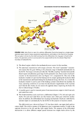
FIGURE 3.34: Axle (front or rear) of a vehicle: differential, final drive based on a single stage
planetary gear (used in heavy equipment applications), and brakes in the final drive housing.
The sun gear is driven by the shaft coming from the differential, the ring gear is fixed to the
frame, the planetary carrier is connected to the output shaft (to the tire-wheel). Reprinted
Courtesy of Caterpillar Inc.
1. The diesel engine which is the mechanical power source for the machine.
2. The automatic transmission with torque converter. The word “automatic” transmis-
sion means that the gear shifting at the planetary stage is handled automatically by
the ECM. The torque converter provides the “flexible coupling” function between the
diesel engine and planetary gear stage. In this particular case, there is also a hydraulic
retarder in the transmission (also see Figure 3.27, component D). The role of the
hydraulic retarder is to provide the braking role by simply spinning the hydraulic fluid
in the transmission and transforming the mechanical energy into heat. As a result, the
hydraulic retarder is used as part of the braking system to decelerate the machine. In
many operating conditions it can meet the deceleration requirement of the machine
such that the disc-brakes do not need to be applied, hence improving the brake life
due to reduced usage of brakes.
3. A transfer gear is used to transmit power from transmission output to both front axle
and center/rear axels.
4. The front/center/rear axels each have a differential (Figure 3.35), left and right axle
shafts. On each axel shaft there are disc-brakes and a final gear reduction mecha-
nism. In addition, the differentials have locking mechanisms which are controlled by
operator input (or automatically by the ECM) for the purpose of traction control.
The differential gear, shown in Figure 3.35, has three shafts: one input shaft and two
output shafts. The relative motion of the planetary gear (component number 3) adds in the
opposite direction to the left and the right output shafts. The purpose of the differential
mechanism is to allow different output speeds between two output shafts driven by the