
Page 215 - Mechatronics with Experiments
P. 215
MECHANISMS FOR MOTION TRANSMISSION 201
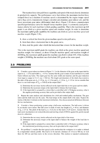
The traction force (rim pull force) capability and speed of the truck directly determine
its productivity capacity. The performance curve that defines the maximum traction force
(rimpull force) as a function of machine speed is determined by the engine torque–speed
curve (lug curve), transmission (torque converter and planetary gear reducer set), and the
lower powertrain gear ratios (differential, final drive). Figure 3.36 shows a manufacturer
specified performance curve for rimpull versus machine speed. A commonly used perfor-
mance criteria for such machines is their grading capability. That is the maximum up-hill
grade it can climb at a given machine speed and machine weight. In order to determine
the maximum uphill grade capability the machine can climb at a given machine speed and
machine weight (Figure 3.36),
1. draw a vertical line from the given machine speed to rim pull curve,
2. from there draw a horizontal line to the grade curve,
3. then, read the grade value which this horizontal line crosses for the machine weight.
This is the maximum uphill grade the machine can climb at the given machine speed and
machine weight. For instance, at about 15 km∕hr machine speed, and machine weight of
40 000 kg, the maximum uphill grade this machine can climb is about 10%. If the machine
weight is 20 000 kg, the machine can climb about 20% grade at the same speed.
3.9 PROBLEMS
1. Consider a gear reducer as shown in Figure 3.1. Let the diameter of the gear on the input shaft be
equal to d = 2.0 in and width w = 0.5 in. Assume that the gear is made of steel and that it is a solid
1
1
frame without any holes. The ouput gear has the same width and material, and the gear reduction
from input to output is N = 5, (d = 10.0 in). The length and diameters of the shafts that extend to
2
the sides of the gears are d = 1.0in, d = 1.0inand l = 1.0in, l = 1.0 in. Let us consider that
s1 s2 s1 s2
there is a net load torque of T = 50 lb in at the output shaft?
L2
1. Determine the net rotary inertia reflected on the input shaft due to two gears and two shafts.
2. Determine the necessary torque at the input shaft to balance the load torque.
3. If the input shaft is actuated by a motor that is controlled with 1∕10 degree accuracy, what is
the angular positioning accuracy that can be provided at the output shaft.
2. Repeat the same analysis and calculations for a belt and toothed pulley mechanism. The gear
ratios and the shaft sizes are the same. The load torque in the output shaft is the same. Neglect the
inertia of the belt. Comment on the functional similarities. Also discuss practical differences between
the two mechanisms.
3. Consider a linear positioning system using a ball-screw mechanism. The ball-screw is driven
by an electric servo motor. The ball screw is made of steel, has length of l = 40 in, and diameter
ls
of d = 2.5 in. The pitch of the lead is p = 4rev∕in (or the lead is 0.25 in∕rev). Assume that the
ls
lead-screw mechanism is in vertical direction and moving a load of 100 lbs against the gravity up and
down in z-direction.
1. Determine the net rotary inertia reflected on the input shaft of the motor.
2. Determine the necessary torque at the input shaft to balance the weight of the load due to
gravity.
3. If the input shaft is actuated by a motor that is controlled with 1∕10 degree accuracy, what is
the translational positioning accuracy that can be provided at the output shaft?
4. For problem 3, consider that the typical cyclic motion that the workpiece is to make is defined
by a trapezoidal velocity profile. The load is to be moved a distance of 1.0inin300ms,towait
there for 200 ms and then move in the reverse direction. This motion is repeated continuously.