
Page 48 - Mechatronics with Experiments
P. 48
JWST499-Cetinkunt
JWST499-c01
34 MECHATRONICS Printer: Yet to Come October 9, 2014 7:39 254mm×178mm
y,v
ϕ
Pitch , q
Velocity vector
x,u α
Roll , p Fl
β
Ft
Fd
Fg
x,y,z = Position coordinates β
= Roll angle
ϕ
u,v,w = Velocity coordinates = Pitch angle
p = Roll rate θ = Yaw angle
θ
Yaw , r q = Pitch rate α
= Angle of attack
z,w r = Yaw rate
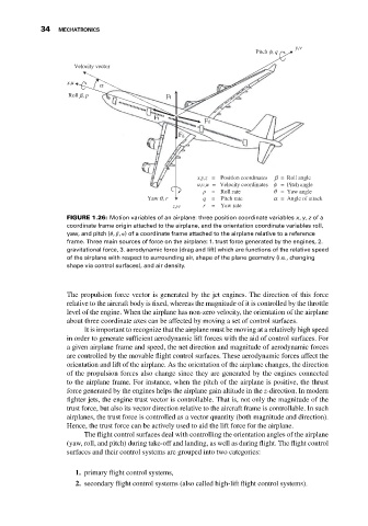
FIGURE 1.26: Motion variables of an airplane: three position coordinate variables x, y, z of a
coordinate frame origin attached to the airplane, and the orientation coordinate variables roll,
yaw, and pitch ( , , ) of a coordinate frame attached to the airplane relative to a reference
frame. Three main sources of force on the airplane: 1. trust force generated by the engines, 2.
gravitational force, 3. aerodynamic force (drag and lift) which are functions of the relative speed
of the airplane with respect to surrounding air, shape of the plane geometry (i.e., changing
shape via control surfaces), and air density.
The propulsion force vector is generated by the jet engines. The direction of this force
relative to the aircraft body is fixed, whereas the magnitude of it is controlled by the throttle
level of the engine. When the airplane has non-zero velocity, the orientation of the airplane
about three coordinate axes can be affected by moving a set of control surfaces.
It is important to recognize that the airplane must be moving at a relatively high speed
in order to generate sufficient aerodynamic lift forces with the aid of control surfaces. For
a given airplane frame and speed, the net direction and magnitude of aerodynamic forces
are controlled by the movable flight control surfaces. These aerodynamic forces affect the
orientation and lift of the airplane. As the orientation of the airplane changes, the direction
of the propulsion forces also change since they are generated by the engines connected
to the airplane frame. For instance, when the pitch of the airplane is positive, the thrust
force generated by the engines helps the airplane gain altitude in the z-direction. In modern
fighter jets, the engine trust vector is controllable. That is, not only the magnitude of the
trust force, but also its vector direction relative to the aircraft frame is controllable. In such
airplanes, the trust force is controlled as a vector quantity (both magnitude and direction).
Hence, the trust force can be actively used to aid the lift force for the airplane.
The flight control surfaces deal with controlling the orientation angles of the airplane
(yaw, roll, and pitch) during take-off and landing, as well as during flight. The flight control
surfaces and their control systems are grouped into two categories:
1. primary flight control systems,
2. secondary flight control systems (also called high-lift flight control systems).