Page 736 - Mechatronics with Experiments
P. 736

722   MECHATRONICS

                                                          A      E  M
                                                   C


                                    Digital I/O           A      E  M
                                                   C


                                                          A      E  M
                                                   C

                                                         (a)
                                                         A       E  M
                                                  C
                                  High speed
                                communication bus
                              (i.e., Sercos, Ethernet, USB)
                                                         A       E  M
                                                  C

                                                         A       E  M
                                                  C

                                                         (b)
                                         Multi axis controller
                                                          A      E  M
                                                   DSP

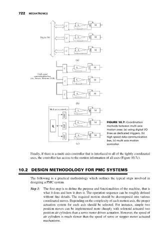
                                                          A      E  M       FIGURE 10.7: Coordination
                                                   DSP                      methods between multi axis
                                                                            motion axes: (a) using digital I/O
                                                                            lines as dedicated triggers, (b)
                                                   DSP    A      E  M       high speed data communication
                                                                            bus, (c) multi axis motion
                                                         (c)                controller.


                              Finally, if there is a multi axis controller that is interfaced to all of the tightly coordinated
                              axes, the controller has access to the motion information of all axes (Figure 10.7c).


                       10.2 DESIGN METHODOLOGY FOR PMC SYSTEMS

                              The following is a practical methodology which outlines the typical steps involved in
                              designing a PMC system.

                              Step 1:  The first step is to define the purpose and functionalities of the machine, that is
                                      what it does and how it does it. The operation sequence can be roughly defined
                                      without fine details. The required motion should be decomposed into various
                                      coordinated moves. Depending on the complexity of each motion axis, the proper
                                      actuation system for each axis should be selected. For instance, simple two
                                      position moves can be implemented more cheaply with solenoid actuated two
                                      position air cylinders than a servo motor driven actuation. However, the speed of
                                      air cylinders is much slower than the speed of servo or stepper motor actuated
                                      mechanisms.
   731   732   733   734   735   736   737   738   739   740   741