Page 744 - Mechatronics with Experiments
P. 744

730   MECHATRONICS
                                                            .
                                                             1 θ     S1        S1

                                 M1
                                                         S1
                                                            .
                                                             2 θ
                                 M2


                                                    (a)
                                            .
                                             1 θ
                                                 Z 1
                                                             Z 2  . 1 θ     M1
                                                        n =     =  .
                                                 Z 2         Z 1   2 θ

                                                                            M2
                                                    .
                                                    2 θ
                                                    (b)

                                                                 2 θ
                                 M1
                                                  θ 1 (t)
                                                θ 2  = f(   1 )θ
                                 M2
                                                                                   1 θ
                                                    (c)
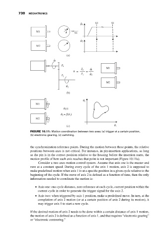
                              FIGURE 10.11: Motion coordination between two axes: (a) trigger at a certain position,
                              (b) electronic gearing, (c) camming.


                              the synchronization reference points. During the motion between these points, the relative
                              positions between axes is not critical. For instance, in pin-insertion applications, as long
                              as the pin is in the correct position relative to the housing before the insertion starts, the
                              motion profile of how each axis reaches that point is not important (Figure 10.11a).
                                   Consider a two axes motion control system. Assume that axis one is the master and
                              runs at a constant speed. During every cycle of the axis 1 motion, axis 2 is supposed to
                              make predefined motion when axis 1 is at a specific position in a given cycle relative to the
                              beginning of the cycle. If the move of axis 2 is defined as a function of time, then the only
                              information needed to coordinate the motion is:

                                  Axis one: one cycle distance, zero reference at each cycle, current position within the

                                  current cycle in order to generate the trigger signal for the axis 2.
                                  Axis two: when triggered by axis 1 position, make a predefined move. In turn, at the

                                  completion of axis 2 motion (or at a certain position of axis 2 during its motion), it
                                  may trigger axis 1 to start a new cycle.

                              If the desired motion of axis 2 needs to be done within a certain distance of axis 1 motion,
                              the motion of axis 2 is defined as a function of axis 1, and that requires “electronic gearing”
                              or “electronic contouring.”
   739   740   741   742   743   744   745   746   747   748   749