
Page 764 - Mechatronics with Experiments
P. 764
750 MECHATRONICS
where V 12 is the voltage potential across the resistor, i(t) is the current across the resistor,
and R is the resistance of the component.
Resistors are marked with a color coding standard. Using this color code, one can
determine the value of a resistor, including its possible tolerance (variation in value due to
manufacturing tolerances). Using a DMM (digital multimeter), the exact value of a resistor
can be easily measured.
An “ideal” capacitor has the following current–voltage relationship,
t
1
V (t) = V (t ) + C ∫ i( )d (11.2)
12 0
12
t 0
which says that the voltage across a capacitor is the initial voltage of the capacitor plus
the integral of the current flowing through the capacitor scaled by the capacitance value C.
V (t) is the voltage across the capacitor at a given time t. Any capacitor will eventually
12
saturate when it stores the maximum charge it can store. In order to limit the current coming
into a capacitor from a DC power supply, a capacitor is never directly connected to a supply,
but through a resistor. A mechanical analogy for a “capacitor” is a “water tank”: initial
water level (water height) in the tank is V (t ), water flow rate into the tank is i(t), cross
12 0
sectional area of the water tank is C, and water level at anytime is V (t).
12
An “ideal” inductor has the following current–voltage relationship,
di(t)
V (t) = L ⋅ (11.3)
12
dt
which says that the voltage across the inductor is proportional to the time rate of change
of current. Another way of interpreting it is that the current is integral of voltage applied
across it. If a constant voltage source is applied, the current would increase as integral of
it, scaled by the inductance.
Kirchoff’s voltage law states that the sum of voltages in a closed path of an electrical
circuit is zero (conservation of voltage potential) at any given instant,
V 14 = V 12 + V 23 + V 34 (11.4)
Kirchoff’s current law states that the algebraic sum of currents at any point in an electrical
circuit is zero, that is, the sum of incoming currents is equal to the sum of outgoing currents
(conservation of electrons),
∑
i + i + i = 0 (11.5)
1
3
2
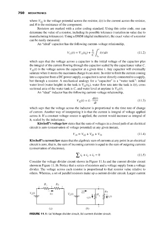
Consider the voltage divider circuit shown in Figure 11.1a and the current divider circuit
shown in Figure 11.1b. Notice that a series of resistors and a voltage supply form a voltage
divider. The voltage across each resistor is proportional to that resistor value relative to
others. Whereas, a set of parallel resistors make up a current divider circuit. Larger current
R 1 R 2
1 2 3 1
R 2
V (t) i(t) V (t) i(t) R
s
s
i (t) 1 i (t)
2
1
2
(a) (b)
FIGURE 11.1: (a) Voltage divider circuit, (b) current divider circuit.