
Page 766 - Mechatronics with Experiments
P. 766
752 MECHATRONICS
A R R
L A
B B
i(t) i(t)
V(t) V(t) C
(a) (b)
FIGURE 11.2: (a) RL circuit (b) RC circuit.
2. Using DMM, measure and determine the direction of current conduction of a diode.
3. Using DMM, measure the continuity across a mechanical switch by turning ON/OFF
the switch (this is called the continuity test between two points in an electrical circuit).
4. Build a voltage divider circuit (Figure 11.1a). Confirm the Kirchoff’s voltage and
current law on the circuit.
5. Build a current divider circuit. Confirm the Kirchoff’s voltage and current law on
the circuit using various closed paths for voltage law and nodes for current law
(Figure 11.1b).
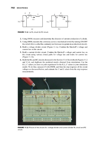
6. Build the RL and RC circuits discussed in the Section 5.5 of the textbook (Figures 11.2
and 11.4), and duplicate the predicted results obtained from simulations. Use the
R, L, C values you have on your experiment for the R, L, C values in your simulation
model. To do that, measure R with DMM, and then the step response of the circuit
voltages as discussed below, and estimate the C and L values from the step response
measurements.
GND
+V
R R 2 R 2
1
R
1
(a) (b)
Voltage divider Current divider
FIGURE 11.3: Picture of the circuits for: voltage divider and current divider RL circuit and RC
circuit.