
Page 771 - Mechatronics with Experiments
P. 771
LABORATORY EXPERIMENTS 757
A B
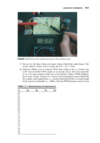
FIGURE 11.6: Picture of the experiment setup for the transistor circuit.
7. Discuss how the input voltage and output voltage relationship would change if the
resistor values R and R were to change, that is R = R = 10 kΩ.
1 2 1 2
8. (Optional) Obtain a way to generate PWM input voltage at the V location, that
in
is PIC microcontroller PWM output, or an op-amp circuit. Select the magnitude
of V to be large enough to fully turn on the transistor. Select a PWM frequency
in
that is large enough compared to a typical electromechanical actuator bandwidth
(for actuator control applications, i.e., actuator bandwidth 100 Hz), yet small enough
for the transistor bandwidth (i.e., 1 MHz). Then the PWM frequency maybe chosen
TABLE 11.1: Measurements for Experiment 2.
V in V AB V BE V CE V DC
0.0
0.1
0.2
0.3
0.4
0.5
0.6
0.7
0.8
0.9
1.0
1.1
1.2
1.3
1.4
1.5
1.6
1.7
1.8
1.9
2.0