
Page 773 - Mechatronics with Experiments
P. 773
LABORATORY EXPERIMENTS 759
R C
V (t) C V (t) V (t) R V (t)
i
i
o
o
(a) (b)
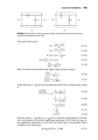
FIGURE 11.7: Circuit of a first-order passive filters: (a) passive low pass first-order filter,
(b) passive high pass first-order filter.
The current in the circuit is
V (t) − V (t)
o
i
i(t) = (11.41)
R
V (s) − V (s)
o
i
i(s) = (11.42)
R
1
R ⋅ i(s) = V (s) − i(s) (11.43)
i
Cs
( 1 )
R + ⋅ i(s) = V (s) (11.44)
i
Cs
i(s) Cs
= (11.45)
V (s) RCs + 1
i
Hence the transfer function between the output voltage and input voltage is
V (s) = 1 (11.46)
o
V (s) RCs + 1
i
V ( jw)
o 1
= (11.47)
V ( jw) 1 + jRCw
i
Notice that when w = 1 rad/s, the magnitude ratio of the output voltage to input voltage
RC
is
|V ( jw)| | 1 |
o
| | = | | (11.48)
| | 1 | |
i
c
| V ( jw) | w=w c = | 1 + jRCw |
RC
| |
| 1 |
= | | (11.49)
| 1 |
| 1 + jRC |
| RC |
1
= (11.50)
2
2 1∕2
(1 + 1 )
1
= √ (11.51)
2
= 0.707 (11.52)
1 1
where the value w = RC rad/s or f = 2 RC Hz is called the cutoff frequency of the filter,
c
c
that is the frequency at which the output signal magnitude is 0.707 times the input sig-
nal magnitude in steady-state. In other words, the output signal is attenuated by 3 dB in
comparison to the input signal.
20 ⋅ log (0.707) =−3.0 dB (11.53)
10