Page 857 - Mechatronics with Experiments
P. 857

®
                                                      ®
                                                MATLAB , SIMULINK , STATEFLOW, AND AUTO-CODE GENERATION  843
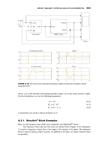


                                          X_cmd                         Position
                              Step        X_fbk  DAC          Force

                                          V_fbk                          Speed
                                            PD control           MKC system


                                                                                              Scope


                                        Commanded position                         Speed
                             1.5                                   1.5

                               1
                                                                    0
                             0.5
                               0                                    –5
                                          Actual position                          Force
                             1.5                                   40
                               1                                   20

                             0.5                                    0
                               0                                  –20
                                                                     0       1      2       3      4
                             FIGURE A.15: PD control and mass-spring-damper system model and simulation results
                                         ®
                             using Simulink .


                             where x (t) is the desired (commanded) position signal, x(t) is the actual position signal.
                                    d
                             For the simulations, we use the following parameters:

                                                            m = 1.0                              (A.4)
                                                           K = (2 ⋅   ) 2                        (A.5)
                                                            p
                                                           K = 0.7 ⋅ 2 ⋅                         (A.6)
                                                            v

                             A simulation case result is shown in Figure A.15.


                                                ®
                             A.2.1 Simulink Block Examples
                                                                                  ®
                             Here we will examine some of the most commonly used Simulink blocks.
                                  The integrator block and unit time delay are shown below (Figure A.16). Integrator,
                              1
                               is used to integrate a signal, that is the output is the integral of the input. The integrator
                              s
                             block is used in analog control systems. In addition to its input, an initial condition must
                             be specified.
   852   853   854   855   856   857   858   859   860   861   862