
Page 862 - Mechatronics with Experiments
P. 862
848 MECHATRONICS
2. “Fcn function and expression block” which operates on scalar or vector inputs but pro-
®
vides a scalar output. This block allows an expression made of MATLAB functions
and operators and input data.
3. “Embedded MATLAB Function Block” which can accept vector input and provide
vector output and implement any function desired. Inputs can be signal inputs in
the Simulink ® environment or variables from the MATLAB ® workspace. Outputs
®
show up at the output port of the Embedded MATLAB Function Block. Parameters
®
can be defined so that they are visible to the block from the MATLAB Workspace
using Tools > Edit Data/Ports. Inputs and Outputs show up both on the Embed-
ded MATLAB ® Function Block and also in the call arguments of the function in
MATLAB ® script. This block is basically a link to a MATLAB ® M-function file
such as the one shown below, and can be very effectively used for simulation of
complicated dynamic systems. When the dynamics of a system get complicated, it
is easier to describe it in MATLAB ® script language (or in C-language using the
®
S-functions) than express it graphically in Simulink . In such cases, the overall
®
structure of the model can be designed in Simulink , and individual complicated
®
sub-systems defined in the “Embedded MATLAB Function Block” in MATLAB ®
script language.
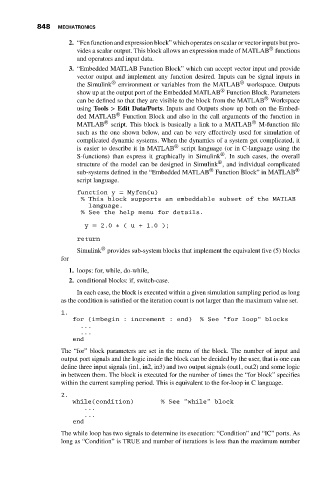
function y = Myfcn(u)
% This block supports an embeddable subset of the MATLAB
language.
% See the help menu for details.
y = 2.0 ∗ ( u + 1.0 );
return
®
Simulink provides sub-system blocks that implement the equivalent five (5) blocks
for
1. loops: for, while, do-while,
2. conditional blocks: if, switch-case.
In each case, the block is executed within a given simulation sampling period as long
as the condition is satisfied or the iteration count is not larger than the maximum value set.
1.
for (i=begin : increment : end) % See "for loop" blocks
...
...
end
The “for” block parameters are set in the menu of the block. The number of input and
output port signals and the logic inside the block can be decided by the user, that is one can
define three input signals (in1, in2, in3) and two output signals (out1, out2) and some logic
in between them. The block is executed for the number of times the “for block” specifies
within the current sampling period. This is equivalent to the for-loop in C language.
2.
while(condition) % See "while" block
...
...
end
The while loop has two signals to determine its execution: “Condition” and “IC” ports. As
long as “Condition” is TRUE and number of iterations is less than the maximum number