Page 866 - Mechatronics with Experiments
P. 866
852   MECHATRONICS
                                                ®
                              A.2.2 Simulink S-Functions in C Language
                                                                                                    ®
                              S-functions are the most powerful method of extending the capabilities of Simulink .
                              S-functions can be written in MATLAB ®  script, C, C++, Fortran and Ada languages.
                              Here, we briefly discuss the S-functions written in C language only. S-functions created
                              in C language are called “MEX-File S-Functions.” Third party companies add value to
                                     ®
                              Simulink through the use of MEX-File S-functions, that is adding hardware device drivers
                              and custom algorithms. S-functions are also supported by the auto-code generation tools
                                                                         ®
                              such as the Real Time Workshop (RTW) or Simulink Coder (SC). The user interface to
                              S-functions can be “masked” to customize its dialog box with the user.
                                   S-functions are used to:
                                                                         ®
                                1. add new algorithmic functionalities to Simulink that are not provided by standard
                                          ®
                                   Simulink blocks,
                                                                       ®
                                2. develop hardware device drivers for Simulink ,
                                                                     ®
                                3. include existing C-functions into Simulink blocks.
                                   There are two main steps to using S-functions in Simulink ®  (see Online Help for
                              further details):

                                1. Create an S-function MEX-file.
                                                  ®
                                2. Add the “Simulink Library Browser > User-Defined Functions > S-Function”
                                   block to your Simulink ®  model, associate it with the desired S-function MEX-file
                                   you created, and setup its parameters, if any.

                              These two steps are integrated into the “Simulink ®  Library Browser > User-Defined
                              Functions > S-Function Builder” block where the user interface dialog of this block
                              guides the user to create the S-function MEX-file as well as associate it with that block in
                                        ®
                              the Simulink model.
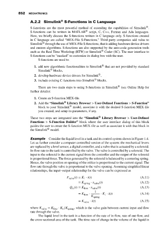
                              Example    Consider the liquid level in a tank and its control system shown in Figure 1.4.
                              Let us further consider a computer controlled version of the system: the mechanical levers
                              are replaced by a level sensor, a digital controller, and a valve that is actuated by a solenoid.
                              In-flow rate to the tank is controlled by the valve. The valve is controlled by a solenoid. The
                              input to the solenoid is the current signal from the controller and the output of the solenoid
                              is proportional force. The force generated by the solenoid is balanced by a centering spring.
                              Hence, the valve position or opening of the orifice is proportional to the current signal. The
                              flow rate through the valve is proportional to the valve opening. Assuming simplified linear
                              relationships, the input–output relationship for the valve can be expressed as

                                                    F   (t) = K ⋅ i(t)                          (A.11)
                                                     valve    1
                                                           = K    ⋅ x   (t)                     (A.12)
                                                              spring  valve
                                                      Q (t) = K  ⋅ x   (t)                      (A.13)
                                                       in     flow  valve
                                                                     1
                                                           = K   ⋅      ⋅ K ⋅ i(t)              (A.14)
                                                              flow         1
                                                                   K
                                                                    spring
                                                           = K    ⋅ i(t)                        (A.15)
                                                              valve
                              where K valve  = K flow  ⋅ K ∕K spring , which is the valve gain between current input and flow
                                                 1
                              rate through the valve.
                                   The liquid level in the tank is a function of the rate of in-flow, rate of out-flow, and
                              the cross-sectional area of the tank. The time rate of change in the volume of the liquid in

