
Page 869 - Mechatronics with Experiments
P. 869
®
®
MATLAB , SIMULINK , STATEFLOW, AND AUTO-CODE GENERATION 855
Scope
+ + 1/mc
– – 1
Desired temperature Relay Gain x s
setting contoller Heater: Q_in
Room temp
Temperature
sensor 1
1/R – +
Heat loss:
Q_out = (1/R) * (T-To)
To
Outside temperature
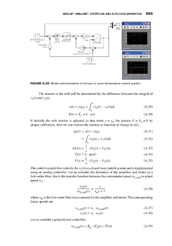
FIGURE A.29: Model and simulation of furnace or room temperature control system.
The tension in the web will be determined by the difference between the integral of
v (t) and v (t),
1
2
t
y(t) = y(t ) + ∫ (v (t) − v (t))dt (A.29)
2
1
0
t o
F(t) = F + k ⋅ y(t) (A.30)
o
If initially the web tension is adjusted so that when y = y , the tension F = F = 0by
0 0
proper calibration, then we can express the tension as function of change in y(t),
Δy(t) = y(t) − y(t ) (A.31)
0
t
= (v (t) − v (t))dt (A.32)
∫ 2 1
t o
1
ΔY(s) = ⋅ (V (s) − V (s)) (A.33)
2
1
s
F(t) = k ⋅ Δy(t) (A.34)
k
F(s) = ⋅ (V (s) − V (s)) (A.35)
1
2
s
The control system that controls the v (t) is a closed loop control system and is implemented
2
using an analog controller. Let us consider the dynamics of the amplifier and motor as a
first-order filter, that is the transfer function between the commanded speed w 2,cmd to actual
speed w ,
2
w (s)
2 1
= (A.36)
w 2,cmd (s) s + 1
m
where is the first-order filter time constant for the amplifier and motor. The corresponding
m
linear speeds are
v 2,cmd (t) = r ⋅ w 2,cmd (t) (A.37)
2
v (t) = r ⋅ w (t) (A.38)
2
2
2
Let us consider a proportional controller,
w 2,cmd (t) = K ⋅ (F (t) − F(t)) (A.39)
p
d