Page 867 - Mechatronics with Experiments
P. 867
®
                                                      ®
                                                MATLAB , SIMULINK , STATEFLOW, AND AUTO-CODE GENERATION  853
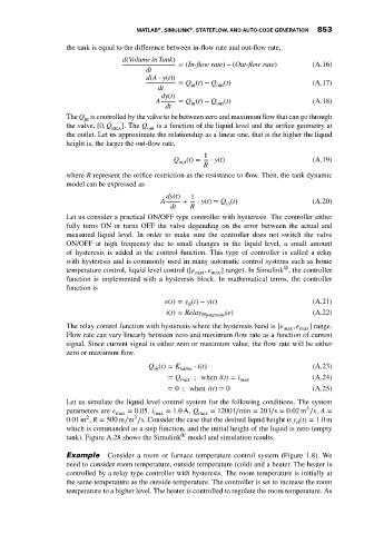
                             the tank is equal to the difference between in-flow rate and out-flow rate,
                                             d(Volume in Tank)
                                                            = (In-flow rate) – (Out-flow rate)  (A.16)
                                                   dt
                                                   d(A ⋅ y(t))
                                                            = Q (t) − Q out (t)                 (A.17)
                                                               in
                                                      dt
                                                       dy(t)
                                                      A     = Q (t) − Q out (t)                 (A.18)
                                                               in
                                                        dt
                             The Q is controlled by the valve to be between zero and maximum flow that can go through
                                  in
                             the valve, [0, Q  ]. The Q  is a function of the liquid level and the orifice geometry at
                                          max      out
                             the outlet. Let us approximate the relationship as a linear one, that is the higher the liquid
                             height is, the larger the out-flow rate,
                                                                   1
                                                          Q   (t) =  ⋅ y(t)                     (A.19)
                                                            out
                                                                  R
                             where R represent the orifice restriction as the resistance to flow. Then, the tank dynamic
                             model can be expressed as
                                                        dy(t)  1
                                                       A     +   ⋅ y(t) = Q (t)                 (A.20)
                                                                        in
                                                         dt    R
                             Let us consider a practical ON/OFF type controller with hysteresis. The controller either
                             fully turns ON or turns OFF the valve depending on the error between the actual and
                             measured liquid level. In order to make sure the controller does not switch the valve
                             ON/OFF at high frequency due to small changes in the liquid level, a small amount
                             of hysteresis is added in the control function. This type of controller is called a relay
                             with hysteresis and is commonly used in many automatic control systems such as home
                                                                                        ®
                             temperature control, liquid level control ([e  , e  ] range). In Simulink , the controller
                                                                max  max
                             function is implemented with a hysteresis block. In mathematical terms, the controller
                             function is
                                                        e(t) = y (t) − y(t)                     (A.21)
                                                              d
                                                        i(t) = Relay    (e)                     (A.22)
                                                                  Hysteresis
                             The relay control function with hysteresis where the hysteresis band is [e max , e max ] range.
                             Flow rate can vary linearly between zero and maximum flow rate as a function of current
                             signal. Since current signal is either zero or maximum value, the flow rate will be either
                             zero or maximum flow.

                                                    Q (t) = K valve  ⋅ i(t)                     (A.23)
                                                     in
                                                         = Q max  ; when i(t) = i max           (A.24)
                                                         = 0 ; when i(t) = 0                    (A.25)

                             Let us simulate the liquid level control system for the following conditions. The system
                                                                                              3
                             parameters are e max  = 0.05, i max  = 1.0A, Q max  = 1200 l∕min = 20 l∕s = 0.02 m ∕s, A =
                                   2
                                                3
                             0.01 m , R = 500 m∕m ∕s. Consider the case that the desired liquid height is y (t) = 1.0m
                                                                                           d
                             which is commanded as a step function, and the initial height of the liquid is zero (empty
                                                            ®
                             tank). Figure A.28 shows the Simulink model and simulation results.
                             Example     Consider a room or furnace temperature control system (Figure 1.8). We
                             need to consider room temperature, outside temperature (cold) and a heater. The heater is
                             controlled by a relay type controller with hysteresis. The room temperature is initially at
                             the same temperature as the outside temperature. The controller is set to increase the room
                             temperature to a higher level. The heater is controlled to regulate the room temperature. As

