
Page 868 - Mechatronics with Experiments
P. 868
854 MECHATRONICS
Scope
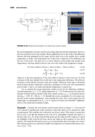
+ + 1/mc
– – 1
Desired temperature Relay Heater: Q_in Gain x s
setting contoller
Room temp
Temperature
sensor 1
1/R +
–
Heat loss:
Q_out = (1/R) * (T-To)
To
Initial position
FIGURE A.28: Model and simulation of a liquid level control system.
the room temperature increases and becomes larger than the outside temperature, there is a
heat loss from the room to the outside. The net added heat rate to the room is the difference
between the heat generated by the heater and the heat loss to the outside since outside
temperature is colder. The temperature rise in the room is function of this difference and
the size of the room. The heat loss is a linear function of the inside and outside room
temperatures. Net heat added (or lost) to the room will result in the temperature change,
(Net Heat Added to Room) = (Heat in Rate) − (Heat out Rate) (A.26)
Q net = Q − Q out (A.27)
in
dT 1
mc = Q − (T − T ) (A.28)
o
in
dt R
where mc is the heat capacitance of the room which is function of the room size, R is the
resistance of the heat transfer from walls due to the temperature difference. The effective
resistance to heat transfer between room and outside is function of the type of dominant
mode of heat transfer (conduction, convection, radiation) as well as the size and insulation
type of walls. T and T are inside and outside temperatures, respectively.
o
Let us simulate the room temperature control system for the following conditions;
◦
◦
desired temperature T = 72 F, initial temperature T = 42 F,allowed error in room tem-
o
d
perature in the hysteresis function of the relay control system, e max = 0, maximum heat-in
rate Q max = 100 , R = 100, mc = 1.0. Initially the room is assumed to be at the same tem-
perature as the outside temperature. After entering the room, that is one second later, the
◦
®
temperature is commanded to be T = 72 F. Figure A.29 shows the Simulink implemen-
d
tation of the model and simulation results.
Example Consider the web tension control system shown in Figure 1.7. The wind-off
roll is driven by another part of the machinery where the speed v (t) is dictated by other
1
considerations. The wind-up roll is driven by an electric motor. This motor is required to
run in such a way that the tension in the web (F) is maintained constant and equal to a
desired value (F ). So, if the wind-off roll speeds up, the wind-up roll is suppose to speed
d
up. Similarly, if the wind-off roll slows down, the wind-up roll is suppose to slow down
quickly. The wind-off roll speed is given as an external input and is not under our control.
The wind-up speed is our controlled variable. Our objective is to minimize the tension error,
e(t) = F (t) − F(t).
d