
Page 860 - Mechatronics with Experiments
P. 860
846 MECHATRONICS
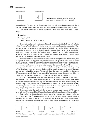
Enabled block Triggered block
FIGURE A.20: Enable and trigger blocks to
make a sub-system enabled and triggered.
block displays the table data as follows: the row vector is treated as the x-axis, and the
column vector is a parameter, and there is a curve for each column-vector in the 2D plot.
Conditionally executed sub-systems can be implemented in one of three different
ways:
1. enabled,
2. triggered, and
3. enabled and triggered sub-systems.
In order to make a sub-system conditionally executed, just include one of, or both
of, the “enabled” and “triggered” blocks in the sub-system and setup the parameters (Fig-
ure A.20). A sub-system can be made enabled by placing an “enable” block in it, triggered
by placing a “trigger” block in it, or it can be both enabled and triggered by placing
both blocks. When the user adds “enable” and/or “trigger” blocks inside a sub-system,
®
Simulink automatically adds an input port for the “enable” and “trigger” signals on the
top line of the block that represents the sub-system.
The enabled block makes the sub-system execute during the time the enable signal
is larger than zero. The triggered subsystem makes the sub-system execute once on every
true trigger signal condition. These two can be combined so that an “enabled and triggered”
sub-system would execute once on the trigger signal if it is also already enabled.
®
Simulink initializes the states in the “enabled” and “triggered” states at the beginning
of the simulation based on the user choices (initial conditions are set to zero if they are
not explicitly defined by the user). We can call these the “start-up” condition of the states.
When the sub-system is disabled and re-enabled/re-triggered again, the states can either be
“held” from the previous run or “reset” to the start-up condition initial values.
In order to simplify the graphical visual display of the connections between blocks,
we can use “Goto” and “From” blocks (Figure A.21). In complicated models, the number
of connection lines and their routing can get very crowded for visual understanding. In
order to simplify that, a signal can be connected to a “Go to” block in one part of the model,
and that signal can be picked-up using a “From” block in another part of the model. That
way, long routing of the connection lines is eliminated.
In order to make the graphical display easier when a large number of I/O lines is
involved, Mux/Demux and Bus-Creater/Bus-Selector blocks can be used (Figure A.22).
Data can be input/output from/to signal sources (i.e., function generator), signal sinks
®
(i.e., scope), MATLAB workspace and files (Figure A.23). The “Signal Builder” block is
a particularly useful signal source tool. It can be used to define custom signal groups rather
quickly and interactively for simulation input signals. Signal Builder provides a graphical
A A
Block 1 Block 2 Block 1 Goto From Block 2
®
FIGURE A.21: Goto and From blocks to simplify line connections in Simulink graphical
model description.